
Robot cleaner

a robot cleaner and cleaner technology, applied in the field of robot cleaners, can solve the problems of needing longer time and more cost for dust or dirt scattered on the floor, and achieve the effects of convenient assembly, simple configuration, and enhanced easiness of dust suction

Inactive Publication Date: 2010-01-26
KYUNGMIN MECHATRONICS
View PDF8 Cites 157 Cited by
  • Summary
  • Abstract
  • Description
  • Claims
  • Application Information

AI Technical Summary

Benefits of technology

"The present invention is a robot cleaner with an auxiliary suction wall for enhancing the ease of sucking dust. The auxiliary suction wall is installed around the dust suction inlet and is movable between a position near the floor and a position away from the floor. It is formed in a simple configuration and reduces fabrication and assembly costs. The robot cleaner with the auxiliary suction wall can run by itself and remove dust or dirt from the floor, making the cleaning process easier."

Problems solved by technology

However, with an opening of dust suction inlet formed small, it will need longer time and more cost for dust or dirt scattered on floor to be inhaled through such dust suction inlet.

Method used


Image

  • Robot cleaner
  • Robot cleaner
  • Robot cleaner

Examples


Embodiment Construction

[0015]Hereinafter, a robot cleaner according to preferred embodiment of the present invention will be described in detail with reference to appended drawings.

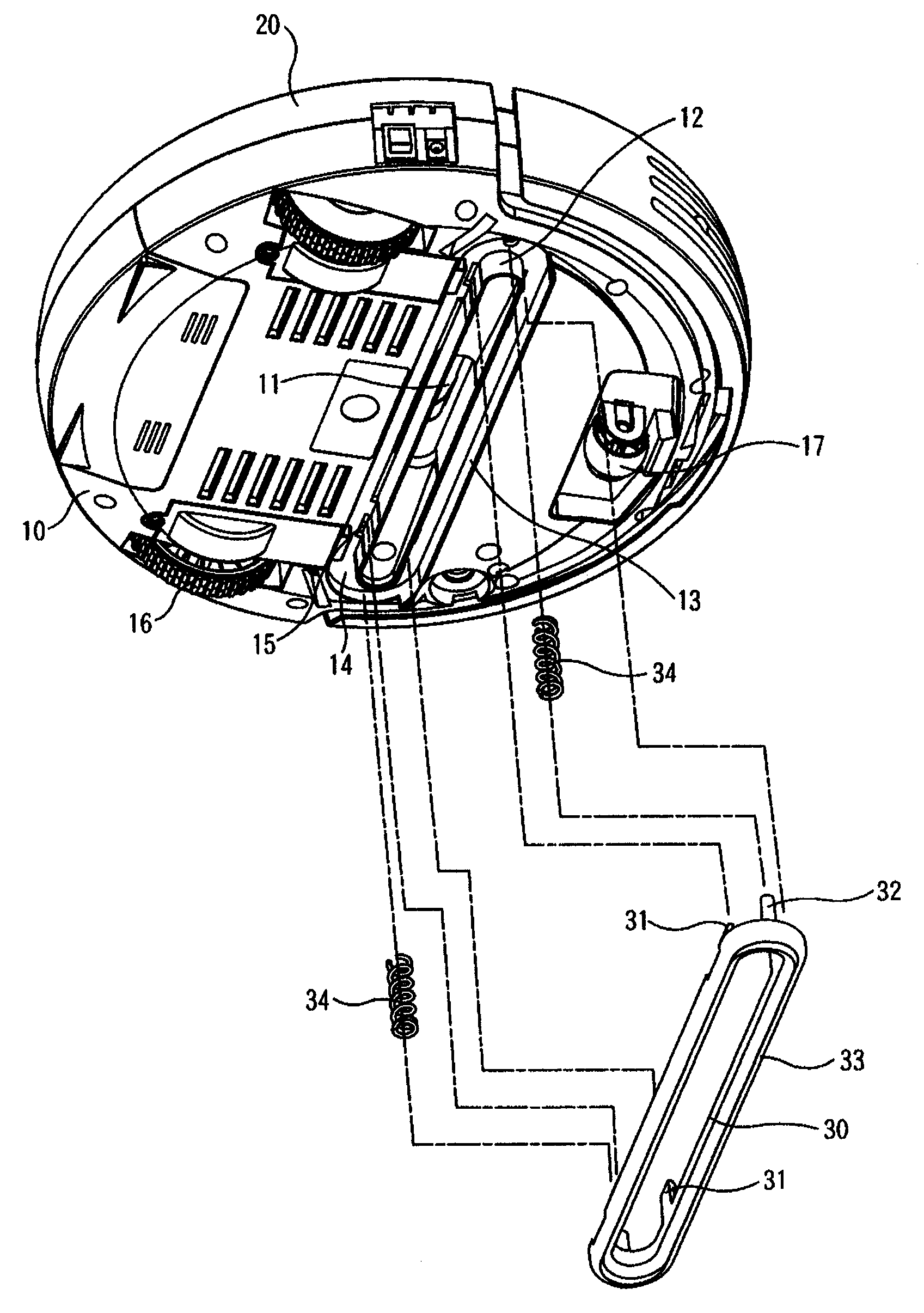
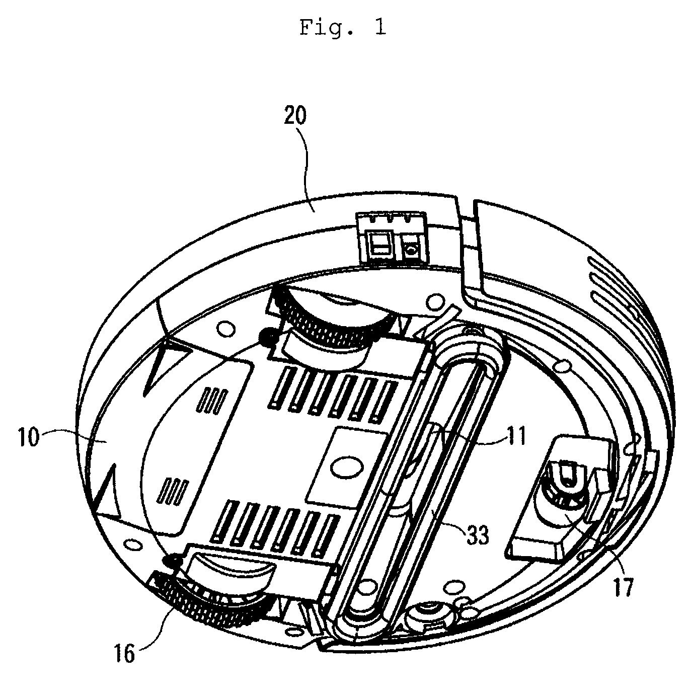
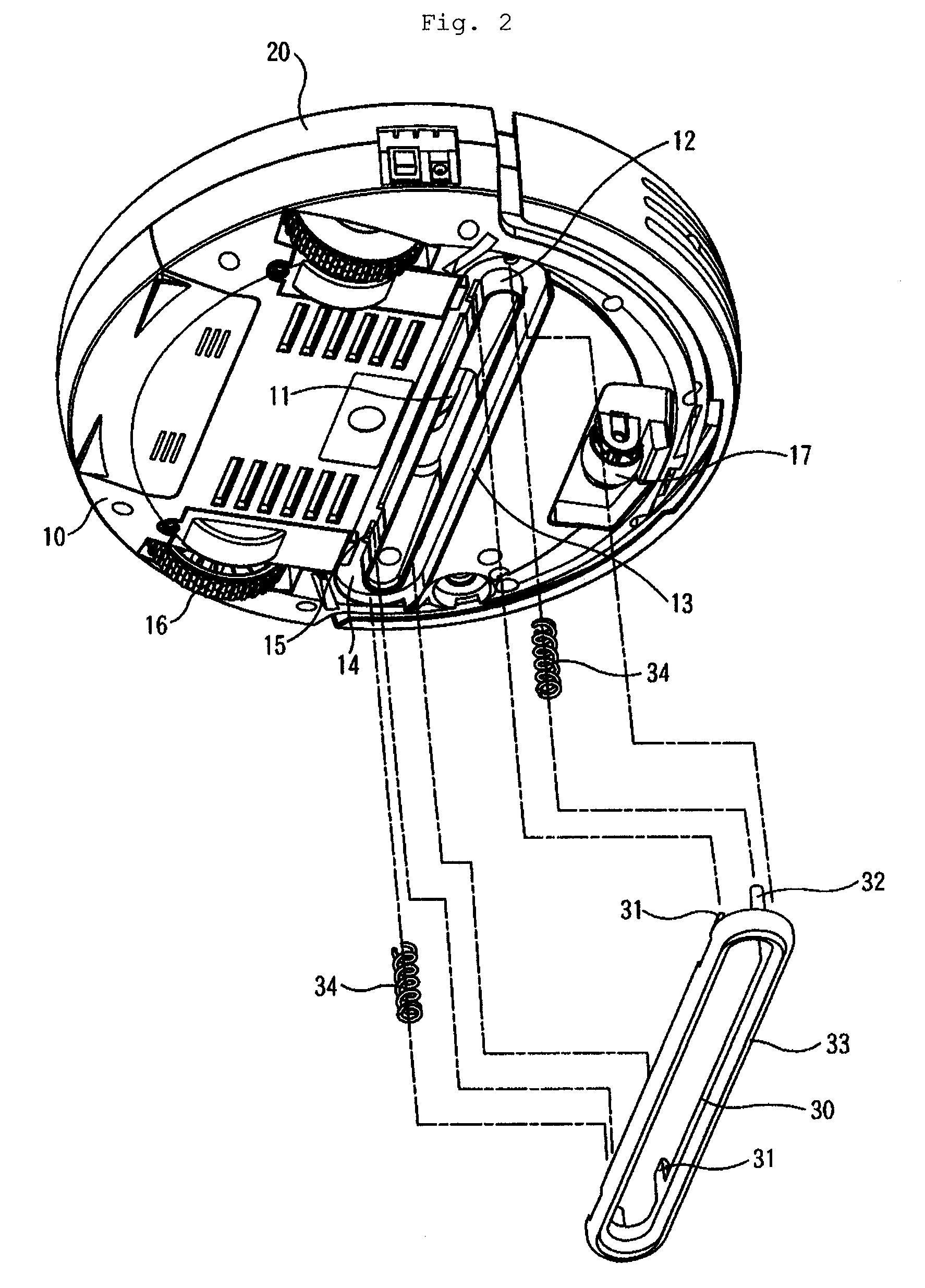
[0016]Referring to FIGS. 1 to 4, a robot cleaner according to the present invention, furnished with a base case 10 and a top case 20 covering on top of said base case 10 can run by itself along a prescribed path, removing dust or dirt scattered on floor.

[0017]Said base case 10 is equipped at upper portion thereof with a driving part (not shown in Figures) for running and a suction part (not shown) for removing dust or dirt, and is formed at one side thereof with a dust suction aperture 11 to which a dust suction inlet 18 is inserted for inhaling dust or dirt from floor (F) into said suction part.

[0018]Detailed configurations of said driving part and suction part are not different so much and are generalized for conventional robot cleaners; those skilled in the art can easily fabricate various types of such configurations, thus ...


PUM


Abstract

A robot cleaner is mainly comprised of a base case whose upper portion is equipped with a driving part for running and a suction part for removing dust or dirt; and a top case covering on top of said base case, wherein said base case is formed at lower portion thereof with an inside vertical wall protruding so as to surround dust suction aperture, and with an outside vertical wall external to said inside vertical wall so that a hollow part may be formed in-between surrounding said inside vertical wall; and an auxiliary suction wall is installed between said inside vertical wall and outside vertical wall in such a manner that said auxiliary suction wall is movable by force of spring external to said inside vertical wall between a No. 1 position locating toward floor (F) and a No. 2 position locating withdrawn from said No. 1 position opposite to floor (F), said auxiliary suction wall being positioned toward floor (F) when no external forces are applied. According to this configuration, it is easy and convenient to install the auxiliary suction wall around dust suction inlet for enhancing easiness in dust suction.

Description

TECHNICAL FIELD[0001]The present invention relates generally to a robot cleaner, and more particularly to a robot cleaner which is furnished with an auxiliary suction wall installed around dust suction inlet for enhancing easiness in suction of dust.BACKGROUND ART[0002]Robot cleaner in general is an automatic cleaner for cleaning a certain area automatically by running itself around the area, removing dust or dirt out of floor without user's direct manipulation.[0003]In such robot cleaner as described above, a dust suction inlet is set inserted at dust suction aperture formed at one side of the base case thereof, and a variety of dust or dirt scattered on floor can be sucked by this dust suction inlet into a dust box formed within the robot cleaner.[0004]As for said dust suction inlet, if the opening thereof were formed big so as to suck dust easily through said dust suction inlet, sucking power thereof would rather become weak. This is the reason why the opening thereof is generall...

Claims


Application Information

Patent Timeline
Patent Type & Authority Patents(United States)
IPC IPC(8): A47L9/00
CPCA47L9/02A47L2201/00A47L9/06
Inventor JANG, SEUNG-RAK
Owner KYUNGMIN MECHATRONICS
Learn More