Porous tendon anchor

a tendon and anchoring technology, applied in the field of tendon anchoring, can solve the problems of affecting the healing or loosening of the interference fixation, affecting the healing effect, and causing the morbidity of the donor knee joint,

Inactive Publication Date: 2010-01-19
HOWMEDICA OSTEONICS CORP
View PDF51 Cites 24 Cited by
  • Summary
  • Abstract
  • Description
  • Claims
  • Application Information

AI Technical Summary

Benefits of technology

[0011]It is another aspect of the invention to provide a tendon anchor which can expand externally under load to securely anchor the tendon within the bone tunnel or within a tunnel from within an implant.
[0013]When the entire tendon anchor is made from the titanium foam, it has been shown to host new bone ingrowth and ongrowth when implanted in bone with new tendon-like tissues growing in the pores of the inside of the tendon anchor. Thus the titanium foam anchor acts as an interface between the bone and tendon. The tendon anchor can be made in the form of a tube and a tendon graft can be passed through the tube and can be fixed to the end of the tube by passing the Bunnell criss-cross stitch through the poles on the tube, which is then tightly fit into the bone tunnel. The suture can also be fixed outside the bone tunnel in any manner. To avoid the possible difficulty in passing the tendon graft through the tube, the tube can be fabricated in two halves.
[0014]Preferably, the device consists of two half tubes split along a small angle wedge creating a first and a second part. In the preferred embodiment the first and second parts are not identical but form a tube of constant diameter when longitudinally aligned. The internal diameter of the tube consists of a tapered cone with multiple barbs locking against the direction towards the larger diameter. After the bony anchoring site is drilled to create a bore, the larger end of one half tube is inserted into the bone, the tendon with suture attached at the end is inserted and the suture is passed through the exit hole in the bore. The smaller end of the second half of the tube is then inserted with force which will lead to the expansion of the two half tubes due to the wedge split. The tendon is pulled against the inner taper of the tubular body which will further expand the foam tube for tight contact to the tendon and the bone. The tubular body can have internal barbs to help prevent the tendon from slipping out. The final lock is achieved by fixing the suture anchor to an anchor outside the bone tunnel.

Problems solved by technology

Although the use of a bone-tendon-bone graft may provide the advantage of effective healing due to the efficient integration of the bone graft to the bone host, the harvesting of a bone-tendon-bone graft typically results in extensive morbidity to the donor knee joint.
However, it has been found to be more difficult to effectuate and maintain accurate fixation of such grafts throughout the healing period where high-tension forces of the knee may act to disrupt the graft construct.
Such a system may result in the tendon being damaged which can result in impeded healing or loosening of the interference fixation.

Method used


Image

  • Porous tendon anchor
  • Porous tendon anchor
  • Porous tendon anchor

Examples


Embodiment Construction

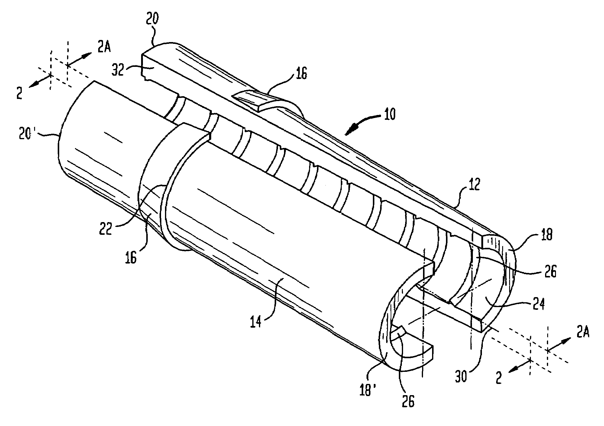
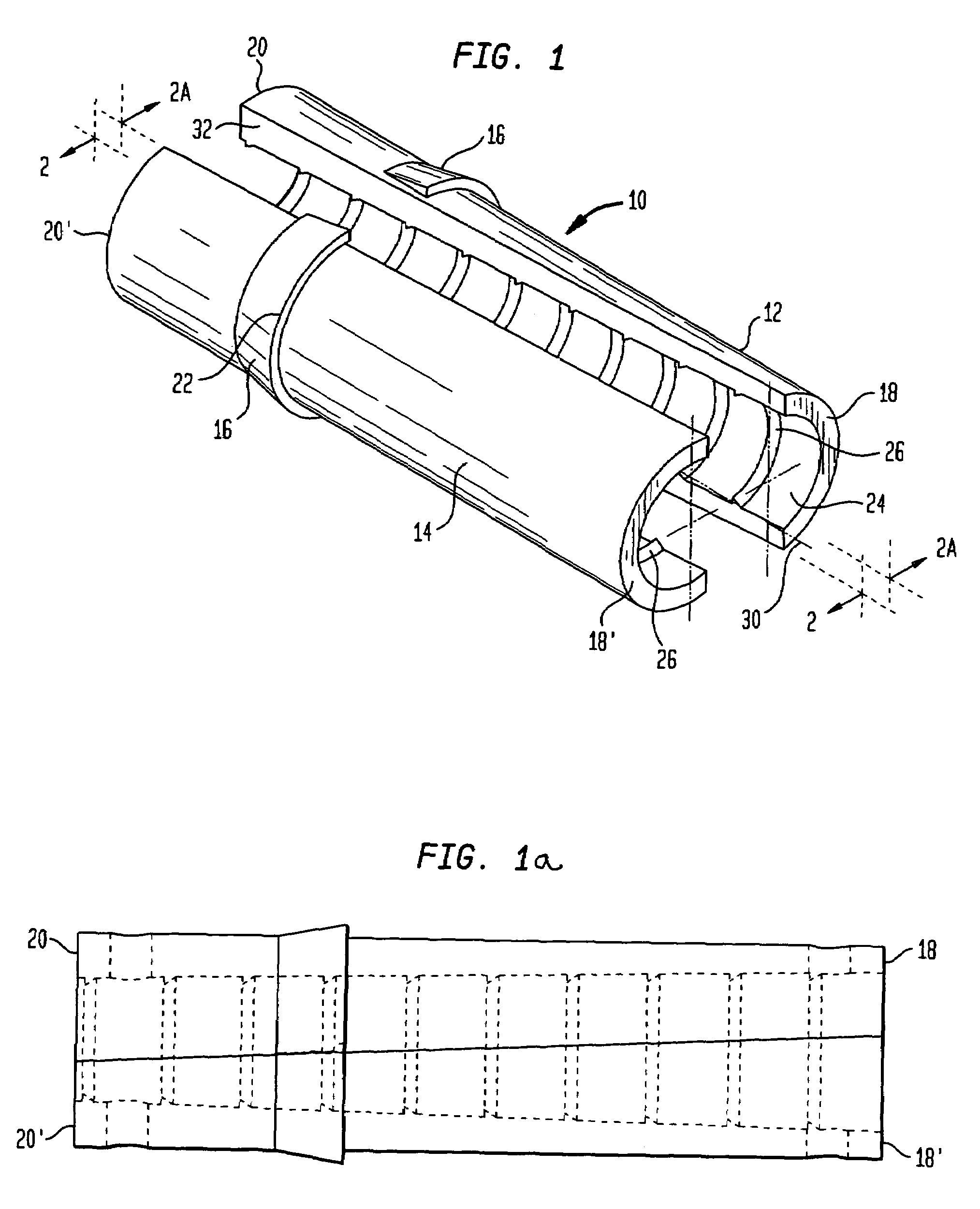
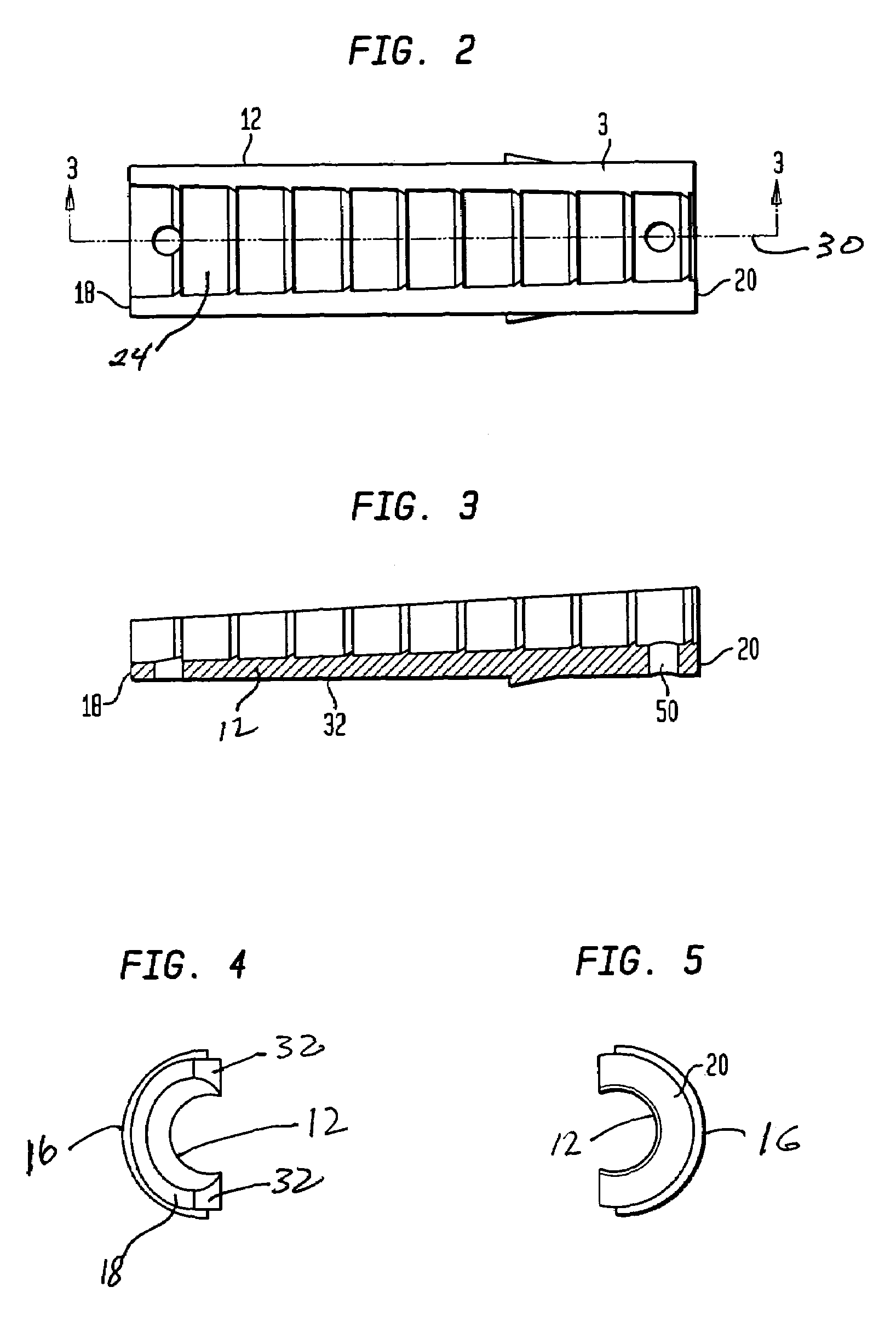
[0027]Referring to FIGS. 1 and 1a there are shown isometric views and side views of the two-piece tendon anchor generally denoted at 10. Tendon anchor 10 consists of a first part 12 and a second part 14 which are generally wedge-shaped such that movement of part 12 with respect to part 14 increases the overall diameter of the anchor 10. Each part 12 and 14 includes an outer circumferential ridge 16 located intermediate a first end 18 and 18′ of the first and second part 12 and 14 respectively and a second end 20 and 20′ of 12 and 14 respectively. Ridge 16 has a relatively sharp edge 22 designed to imbed itself in the bone as the anchor 10 expands by the relative movement of part 12 with respect to part 14. In first part 12 end 20 is the thicker wedge wall and in second part 14 end 20′ is the thicker wedge wall. Ends 18 and 18′ are the thinner wedge wall since the inner diameter of the anchor is larger at this end. The circumference of parts 12 and 14 is tapered. End 18′ is the large...


PUM


Abstract

An anchor for fixing a ligament or tendon replacement in a bore formed in a bone has two parts. A first partially cylindrical part has a semi-circular bore therethrough extending along an axis. The bore tapers conically inwardly with respect to the axis from a larger radius at a first end to a smaller radius at second end. The outer surface of the partially cylindrical part is spaced at a constant radius from the axis between the first and second ends. The first and second parts have side walls formed between the bore and the outer surface which walls extend along a plane which forms an angle with respect to the central axis. When the two parts are engaged along their side wails and slide with respect to the axis the outer diameter of the two parts enlarges.

Description

BACKGROUND OF THE INVENTION[0001]The present invention relates to a tendon anchor to be used within the knee or other parts of the body.[0002]The present invention is directed to the reconstruction of the anterior cruciate ligament (ACL) and the posterior cruciate ligament (PCL). The ACL helps stabilize the knee joint, and prevents posterior displacement of the femur on the tibia in hyperextension of the knee joint.[0003]The ACL is sometimes torn during sports or as a result of traumatic stresses. Ligament reconstruction with allograft or autograft tissue has been shown to improve joint function and provide long term improvement in restoration of physical activity. A typical surgical procedure for ligament replacement and reconstruction involves obtaining a tissue graft or a suitable synthetic graft to replace the damaged ligament. A graft may come from either another part of the patient's body (autograft), from a cadaver donor (allograft), or the graft may be synthetically manufact...

Claims


Application Information

Patent Timeline
Patent Type & Authority Patents(United States)
IPC IPC(8): A61B17/84
CPCA61B17/686A61F2/0811A61F2002/0829A61F2002/0864A61F2002/0882B33Y80/00
Inventor ZHANG, RENWENLAWRYNOWICZ, DANIELDONG, NICHOLAS NAI GUANG
Owner HOWMEDICA OSTEONICS CORP
Why Eureka
Try Eureka