Eureka AIR delivers breakthrough ideas for toughest innovation challenges, trusted by R&D personnel around the world.

Receiver

a receiver and receiver technology, applied in the field of receivers, can solve the problems of degrading the degrading the line quality of broadband wireless communication, and already changing the reception environment of the radio wave, so as to achieve the effect of good reception state and degrading the reception sta

Inactive Publication Date: 2009-12-22
FUJITSU GENERAL LTD
View PDF23 Cites 13 Cited by
  • Summary
  • Abstract
  • Description
  • Claims
  • Application Information

AI Technical Summary

Benefits of technology

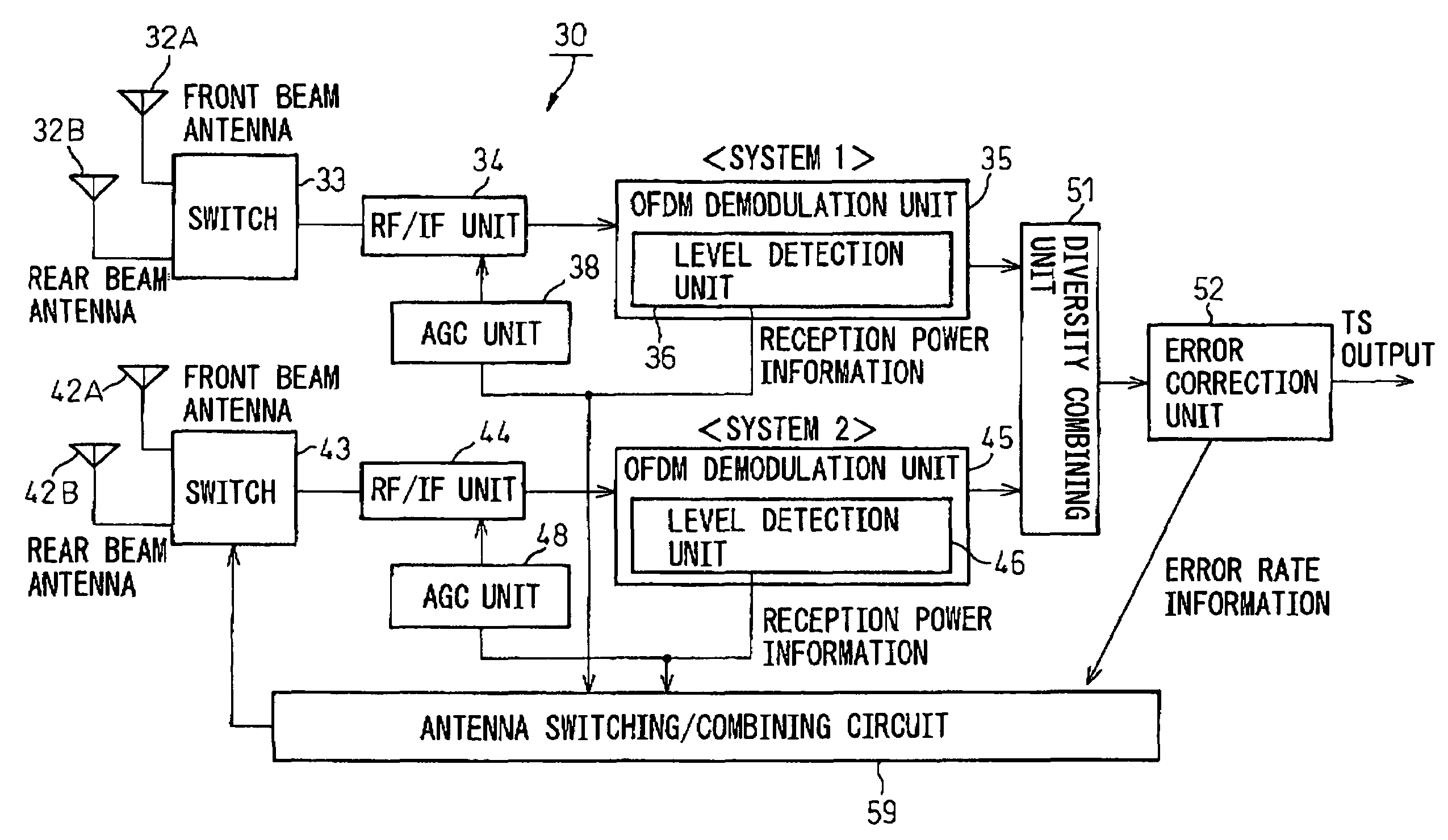
[0026]Further, a second object of the present invention is to provide a receiver for acquiring a reception power at the time of detecting deterioration of the state of reception and switching to a directional antenna having a smaller reception level than an excessively large reception power.
[0027]Further, a third object of the present invention is to provide a receiver provided with means for suppressing fluctuation of the reception level before and after switching of an antenna in the receiver and reducing the effect of antenna switching on the receiver.
[0031]According to the present invention, at the time of deterioration of reception due to excessive reception power, the directional antennas can be switched to improve the reception performance. In this way, by suitably controlling the reception power of the radio wave at the stage of the antenna input, it becomes possible to provide improved reception performance by using just the range of good characteristics of the reception tuner and other electric circuits in a strong field.
[0033]According to the present invention, fluctuation of the reception level before and after the switching of antennas is suppressed, so the degradation of the state of reception due to the switching of antennas is prevented, and it becomes possible to maintain a good state of reception.

Problems solved by technology

Frequency selective phasing causes a problem in that it degrades the line quality in broadband wireless communication.
Especially, due to Doppler shift, when a high speed moving vehicle receives a digital television signal modulated by the OFDM scheme, if there is frequency selectivity in the multipath, the reception property will be degraded due to inter-carrier interference (ICI).
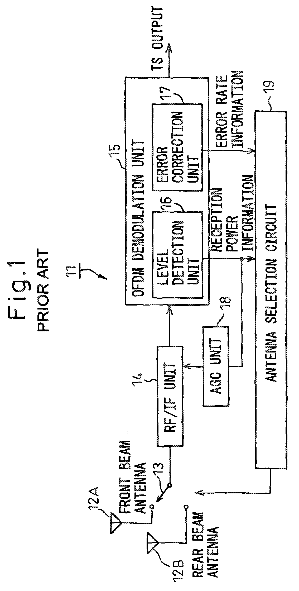
If, however, like in above conventional examples, employing the routine of successively switching to a plurality of directional antennas for predetermined periods to detect mean reception levels and comparing these to select the antenna having the best orientation, when for example a vehicle moving at a high speed on streets surrounded by high-rise buildings switches to the desired directional antenna based on the results of the comparison, there would be the problems that the reception environment of the radio wave would already be changing and therefore the state of reception of the vehicle might not be improved or might even be degraded.
Especially, when receiving a digital television signal, there has been the problem that not only does reception deteriorate like with an analog television signal, but also loss of synchronization etc. can lead to reception suddenly being disabled.
Further, according to the example of FIG. 2 (S15), there has been the problem that this poor state of reception has to be endured for a certain time (several seconds to several tens of seconds).
As a result, there has been the problem that reception was degraded or reception was disabled.
In this case, the combination of the strong field of the radio wave and the directional antenna 203 facing the direction of arrival of that radio wave results in the reception level of the radio wave becoming excessive.
There was therefore the problem that this excessive reception level exceeded the permissible operating ranges of the amplifier, attenuator, etc. of the reception tuner mounted in the vehicle 202 and caused waveform distortion, harmonic noise, etc., and rather caused deterioration of the reception property of the digital television broadcast signal.
Further, if just, like in the above conventional example, successively switching to a plurality of directional antennas for predetermined periods to detect their mean reception levels and comparing them to simply switch to the antenna having the best orientation, there has been the problem that the reception level greatly fluctuates before and after switching the antenna.
Further, there has been the problem that a delay arose until the reception level was stabilized, therefore a sharp change of level of the reception signal occurred and exceeded the permissible difference of sampling of the next stage A / D converter etc. causing deterioration of the state of reception and consequently causing bit error.

Method used


Image

  • Receiver
  • Receiver
  • Receiver

Examples


second embodiment

[0107]FIG. 9 shows the present invention.

[0108]In this example, first, the tuner 1 side (system 1 side) is switched to the front beam antenna FR (21A), and the tuner 2 side (system 2 side) is switched to the rear beam antenna RL (22B) (S0202 and S0203).

[0109]In this state, the tuners 1 and 2 (24-1 and 24-2) detect the states of reception (S0202 and S0204) and compare the states of reception (S0205). If the reception level of the tuner 1 is larger than the reception level of the tuner 2 (tuner 1>tuner 2), it is judged that the radio wave is being received from the front of the vehicle, and the front beam antenna FR (21A) of the tuner 1 side and the front beam antenna FL (22A) of the tuner 2 side are switched to (S0206).

[0110]Conversely, if the reception level of the tuner 1 is smaller than the reception level of the tuner 2 (tuner 12), it is judged that the radio wave is being received from the rear of the vehicle, and the rear beam antenna RR (21S) of the tuner 1 side and the rear b...

third embodiment

[0112]FIG. 10 shows the present invention.

[0113]In this example, first, the tuner 1 side (system 1 side) is switched to the front beam antenna FR (21A), and the tuner 2 side (system 2 side) is switched to the front beam antenna FL (22A) in the same way as the above (S0301).

[0114]In this state, the tuners 1 and 2 (24-1 and 24-2) detect the reception levels (S0302). In this example, when the radio wave from the front of the vehicle exceeds a predetermined reference value, the state of reception thereof is maintained (S0303 and S0304), while conversely, when it is the reference value or less, the tuner 1 side is switched to the rear beam antenna RR (21B) and the tuner 2 side is switched to the rear beam antenna RL (22B) (S0305).

[0115]In this example, both of the systems 1 and 2 detect the states of reception by using directional antennas of the same orientation, therefore there is the advantage that frequency division diversity can be used even while moving at a high speed. Due to this...

fifth embodiment

[0122]FIG. 12 shows the present invention.

[0123]This example is a modification of the third embodiment shown in FIG. 10, but further is predicated on the reception environment of FIG. 11. Accordingly, steps 50501 to S0503 of this example are the same as S0401 to S0403 of FIG. 9, so no further explanation is given here.

[0124]In this example, when detecting deterioration of reception (S0503), the tuner 1 side (system 1 side) is switched to the front beam antenna FR (21A) and the tuner 2 side (system 2 side) is switched to the front beam antenna FL (22A) in the same way as the above (S0504).

[0125]In this state, the tuners 1 and 2 (24-1 and 24-2) detect the states of reception (S0505). Here, the overall reception level detected at the tuner 1 and the tuner 2 (S0505) and the state of reception before the start of the present control (S0502) are compared (S0506). As a result, if the difference of the reception levels of the two is smaller than a predetermined reference value, it is judged...


PUM


Abstract

A receiver for receiving a digital signal of a radio wave etc. modulated by the OFDM scheme, provided with a first reception unit having a first antenna set comprising a plurality of directional antennas, a first switching / combining unit for outputting a signal received at one directional antenna of said first antenna set or a combined signal of signals received by at least two directional antennas in the first antenna set; a second reception unit having a second antenna set comprising a plurality of directional antennas, a second switching / combining unit for outputting a signal received at one directional antenna of the second antenna set or a combined signal of signals received by at least two directional antennas in the second antenna set; and a switching / combining control unit for controlling the switching / combining operation of the reception signals of the first switching / combining unit and / or the second switching / combining unit based on the states of reception in the first reception unit and the second reception unit.

Description

[0001]This application claims priority to Japanese Patent Application No. JP-2004-028005 filed on Feb. 4, 2004 which claims priority to JP-2004-074695 filed Mar. 16, 2004 which claims priority to JP-2004-077962 filed on Mar. 18, 2004.BACKGROUND OF THE INVENTION[0002]1. Field of the Invention[0003]The present invention relates to a receiver, more particularly relates to a receiver for receiving a digital signal such as a radio wave modulated by the orthogonal frequency division multiplexing (OFDM) scheme.[0004]2. Description of the Related Art[0005]The OFDM scheme is used for ground wave digital television broadcasting. The OFDM scheme is a type of a multi-carrier transmission system and transmits a signal obtained by quadrature amplitude modulation (QAM) of 5300 sub-carriers arranged at intervals of for example 1 kHz.[0006]The multi-carrier system is known as a system generally excellent in durability with respect to frequency selective phasing. Frequency selective phasing causes a ...

Claims


Application Information

Patent Timeline
Patent Type & Authority Patents(United States)
IPC IPC(8): H04M1/00H04B7/08
CPCH04B7/0814H04B7/0874H04B7/088H04L1/02H04L27/2647
Inventor KURIOKA, NOBUYUKI
Owner FUJITSU GENERAL LTD
Why Eureka
Eureka Blog
Learn More