
Microphone attachment device

a technology for attaching devices and microphones, which is applied in the direction of electrical transducers, piezoelectric/electrostrictive transducers, transducer types, etc., can solve the problems of difficult handling of different types of microphone arrangements, inability to provide adequate contact force and contact stroke between the plus terminal, and difficulty in attaching the torsion coil spring to the shaft-shaped support member, etc., to achieve simple and reliable manner, mount reliably and smoothly

Inactive Publication Date: 2009-10-13
SMK CORP
View PDF7 Cites 2 Cited by
  • Summary
  • Abstract
  • Description
  • Claims
  • Application Information

AI Technical Summary

Benefits of technology

[0014]By way of introduction the present invention provides a microphone attachment device that is compact, provides stable features, and is formed from a microphone holder and a socket into which the holder is mounted. The microphone holder has a bull's eye shaped output terminal that holds and supports the microphone in a simple and reliable manner. Terminal members are provided which form reliable connections to a pair of output terminals without the possibility of short circuits between them. The socket can be mounted reliably and smoothly in the microphone holder. The terminal members can connect reliably to the corresponding terminals on a circuit substrate when the socket is attached to the circuit substrate.

Problems solved by technology

However, adequate contact force and contact stroke cannot be provided between the plus terminal and the like of the microphone and the conductor sections of the holder.
Furthermore, when there is electrical contact with the external substrate, positional relationships are defined, making it difficult to handle different types of microphone arrangements.
However, attaching the torsion coil spring to the shaft-shaped support member is not easy.
This is a narrow structure and forming a cut-out large enough to allow easy fitting of the coil is difficult.
This makes it questionable whether adequate strength can be provided.

Method used


Image

  • Microphone attachment device
  • Microphone attachment device
  • Microphone attachment device

Examples


first embodiment

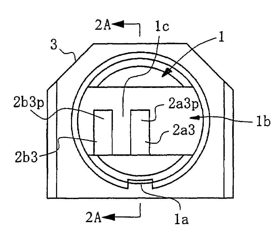
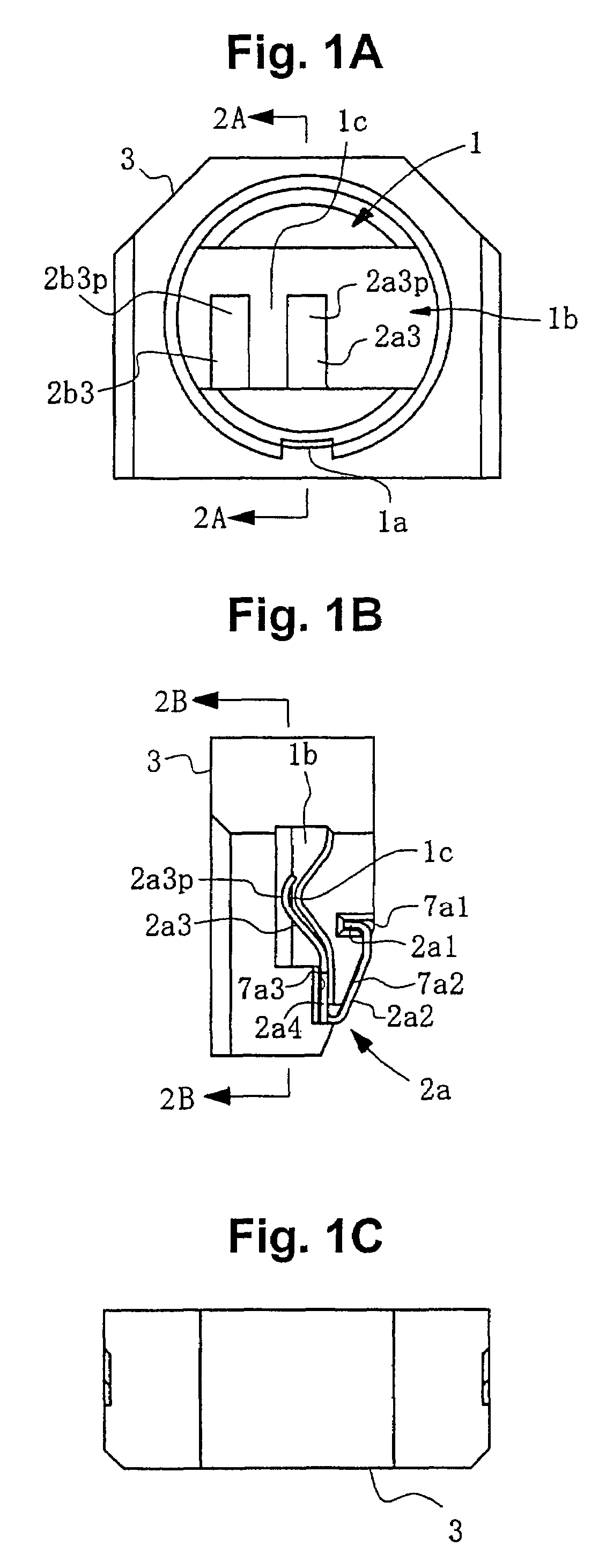
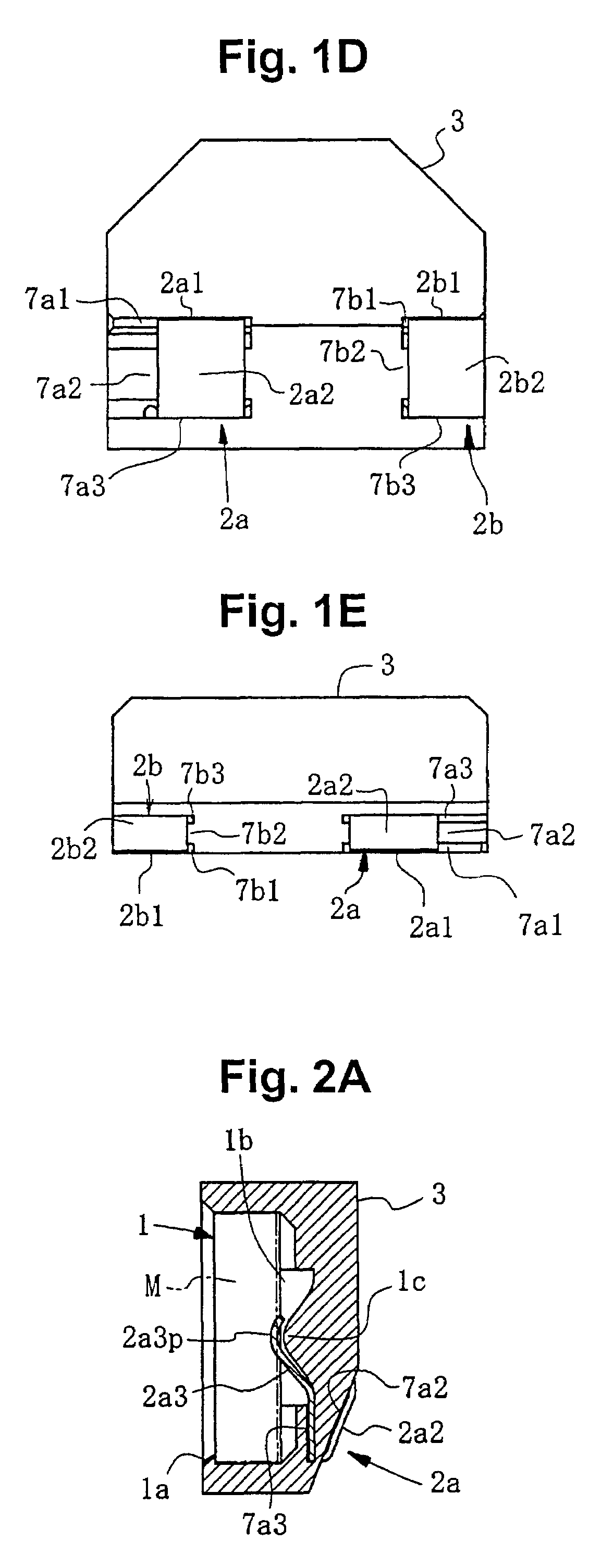
[0073]A microphone attachment device according to this embodiment includes, essentially: a microphone holder holding a microphone M; and a socket holding the microphone holder.

[0074]As shown in FIG. 1(a) through FIG. 1(e), FIG. 2(a), FIG. 2(b), FIG. 8(a), and FIG. 8 (b), the microphone holder is equipped with a microphone holding section 1 that opens to the front surface, a main holder unit 3 formed with a first terminal attachment slit and a second terminal attachment slit into which are inserted from the rear a first terminal member 2a or a second terminal member 2b respectively, and the first terminal member 2a and the second terminal member 2b, which are inserted and secured in the first terminal attachment slit and the second terminal attachment slit. As shown in FIG. 7(a) through FIG. 7(d) and FIG. 8(a) through FIG. 8(c), the socket includes a main socket unit 5 equipped with a holder holding section 4 into which the microphone holder is slid and a first intermediate terminal ...


PUM


Abstract

Presented is device that attaches a microphone to a circuit substrate and includes a main holder unit holding a microphone and a main socket unit holding the main holder unit. Mounted in the main holder unit are inner contact pieces coming into contact with output terminals of the microphone when it is being held outer contact pieces coming into contact with inner contact pieces of first or second intermediate terminal members, and first and second terminal members formed from base sections connected at their bottom ends in a V-shape. On the main socket unit is disposed inner contact pieces, bends, bent from the upper ends thereof, and first and second intermediate terminal members formed as an inverted V-shape member from outer contact pieces formed at the lower ends thereof.

Description

INCORPORATION BY REFERENCE[0001]The present application claims priority under 35 U.S.C. §119 to Japanese Patent Application No. 2004-302959, filed Oct. 18, 2004, in the Japanese language. The content of this application is hereby incorporated by reference in its entirety.FIELD OF THE INVENTION[0002]The present invention relates to a microphone attachment device for reliably connecting and supporting a compact microphone on a circuit substrate and more particularly compact microphones such as electret condenser microphones installed in a portable telephone or digital camera with video recording functions or various other types of wireless devices.BACKGROUND OF THE INVENTION[0003]Japanese Patent Publication No. 2004-20787 discloses a microphone device equipped with a microphone formed with a roughly cylindrical outer perimeter surface shape and a rubber holder surrounding the microphone in a cylindrical shape and supporting it. In this microphone, a main microphone unit is held in a r...

Claims


Application Information

Patent Timeline
Patent Type & Authority Patents(United States)
IPC IPC(8): H04R9/08
CPCH04R11/04
Inventor KOBAYASHI, TSUKASA
Owner SMK CORP
Learn More