Eureka AIR delivers breakthrough ideas for toughest innovation challenges, trusted by R&D personnel around the world.

Suturing device

a suture device and suturing technology, applied in the field of suturing devices, can solve the problems of suturing devices, difficult to reach some suture sites, and inability to use conventional sutures and suturing methods to close an opening

Active Publication Date: 2009-10-13
QUICKPASS
View PDF41 Cites 73 Cited by
  • Summary
  • Abstract
  • Description
  • Claims
  • Application Information

AI Technical Summary

Benefits of technology

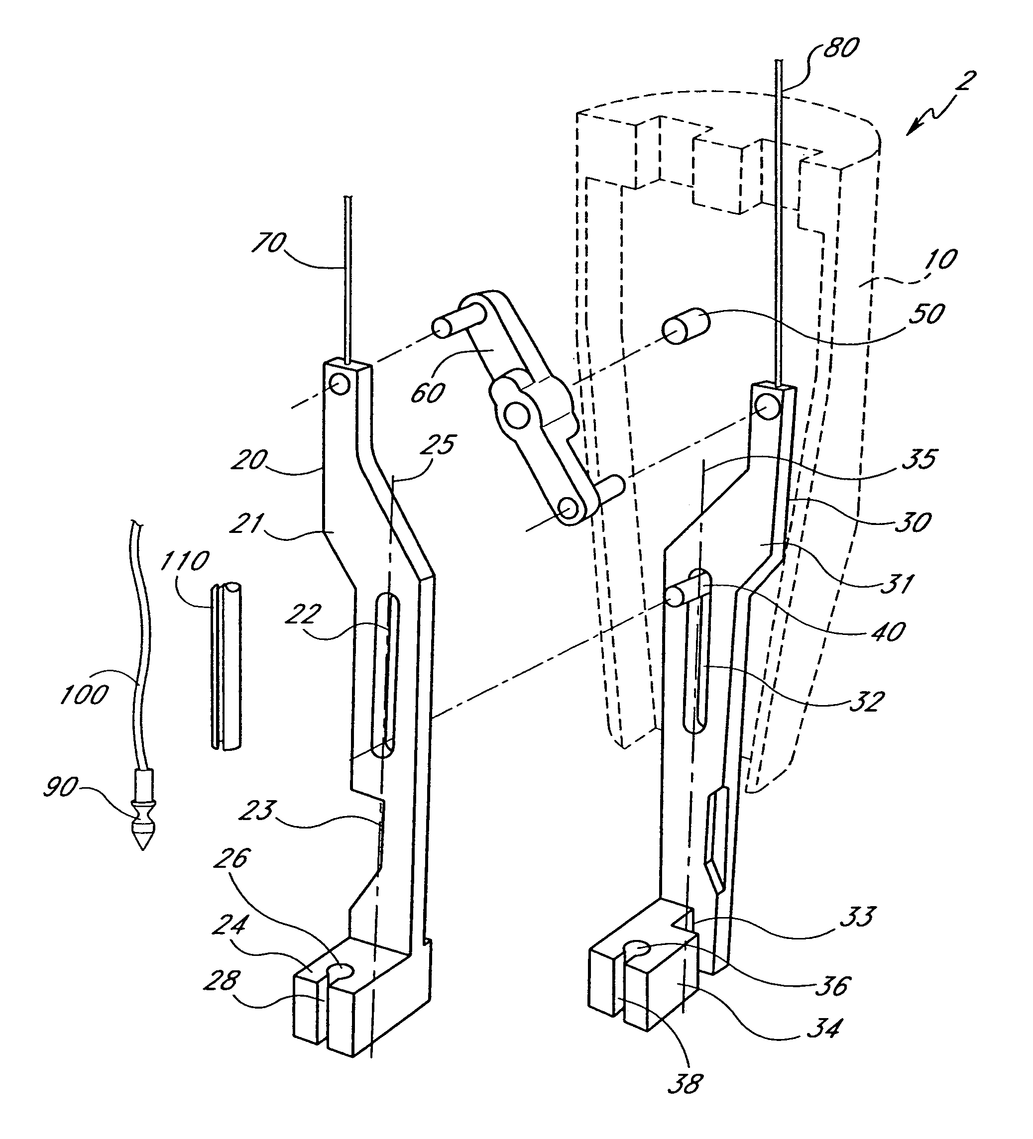
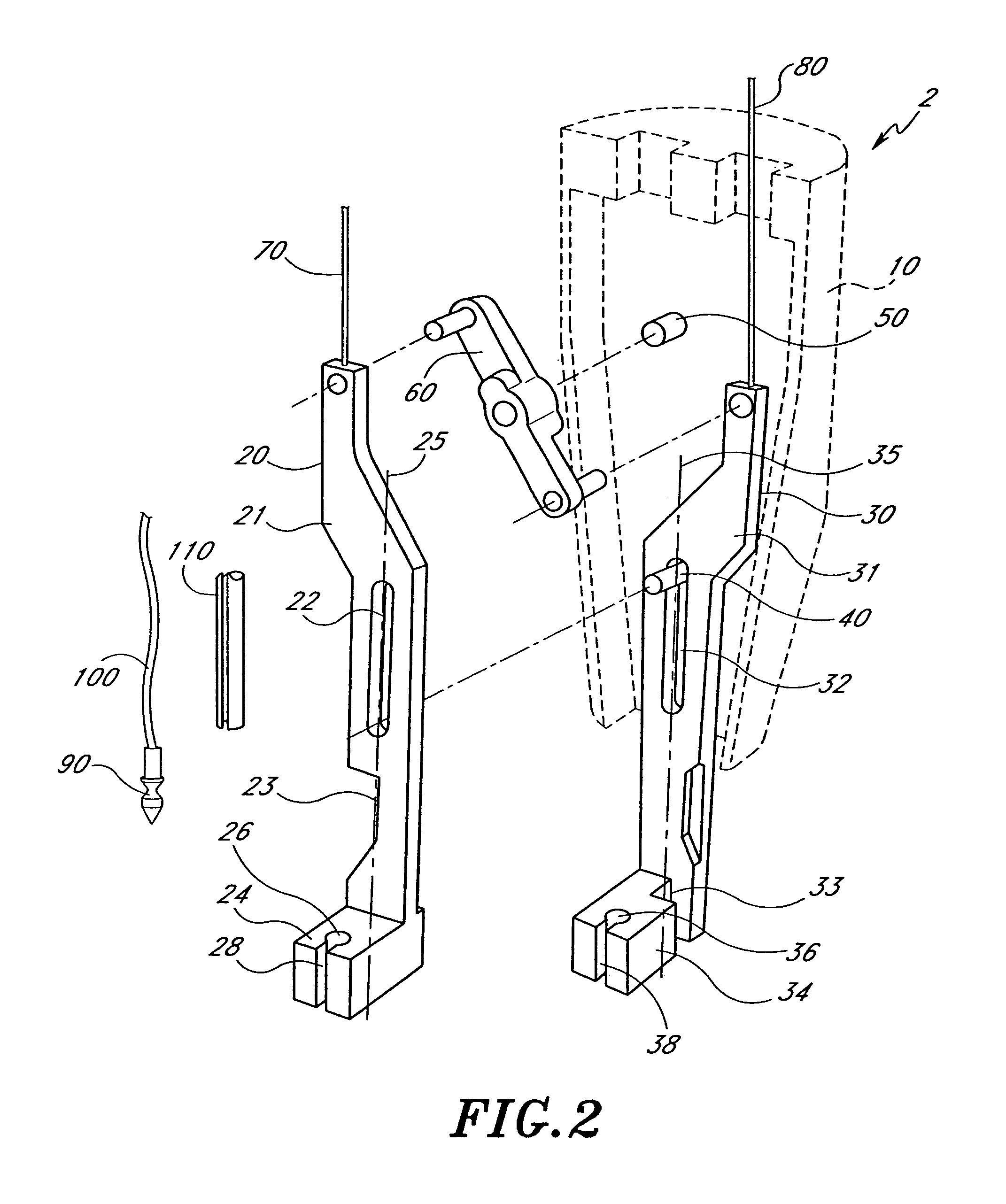
"The present invention provides a device and method for suturing a portion of biological tissue using a suturing device with a needle and a needle driver. The device has a longitudinal axis and a distal needle holder that releasably holds the needle. The needle driver moves longitudinally in a first direction along a path parallel to the longitudinal axis of the device, so that the needle and suture pass through the portion of biological tissue, thereby forming a suture incision through which the suture passes. The needle driver is disengaged from the needle and retracted in the proximal direction away from the needle and the first and second needle holders. The first and second needle holders are laterally withdrawn from the portion of biological tissue, and their positions are exchanged, so that the first needle holder is in a distal position relative to the second needle holder and the needle. The suturing device can be used to suture a portion of biological tissue with greater precision and ease of use."

Problems solved by technology

There are however some circumstances under which it is not feasible to use conventional sutures and suturing methods to close an opening.
It is often difficult to reach some suture sites with existing suturing devices because of the depth of the suture site within the human anatomy, the size of the suture site, and / or the restriction of surrounding organs and tissue.
For example, where the tissue to be sutured is within the patient's thorax (such as for an end-to-side anastomosis in a cardiac bypass procedure), traditional methods of suturing are invasive and time consuming.

Method used


Image

  • Suturing device
  • Suturing device
  • Suturing device

Examples


Embodiment Construction

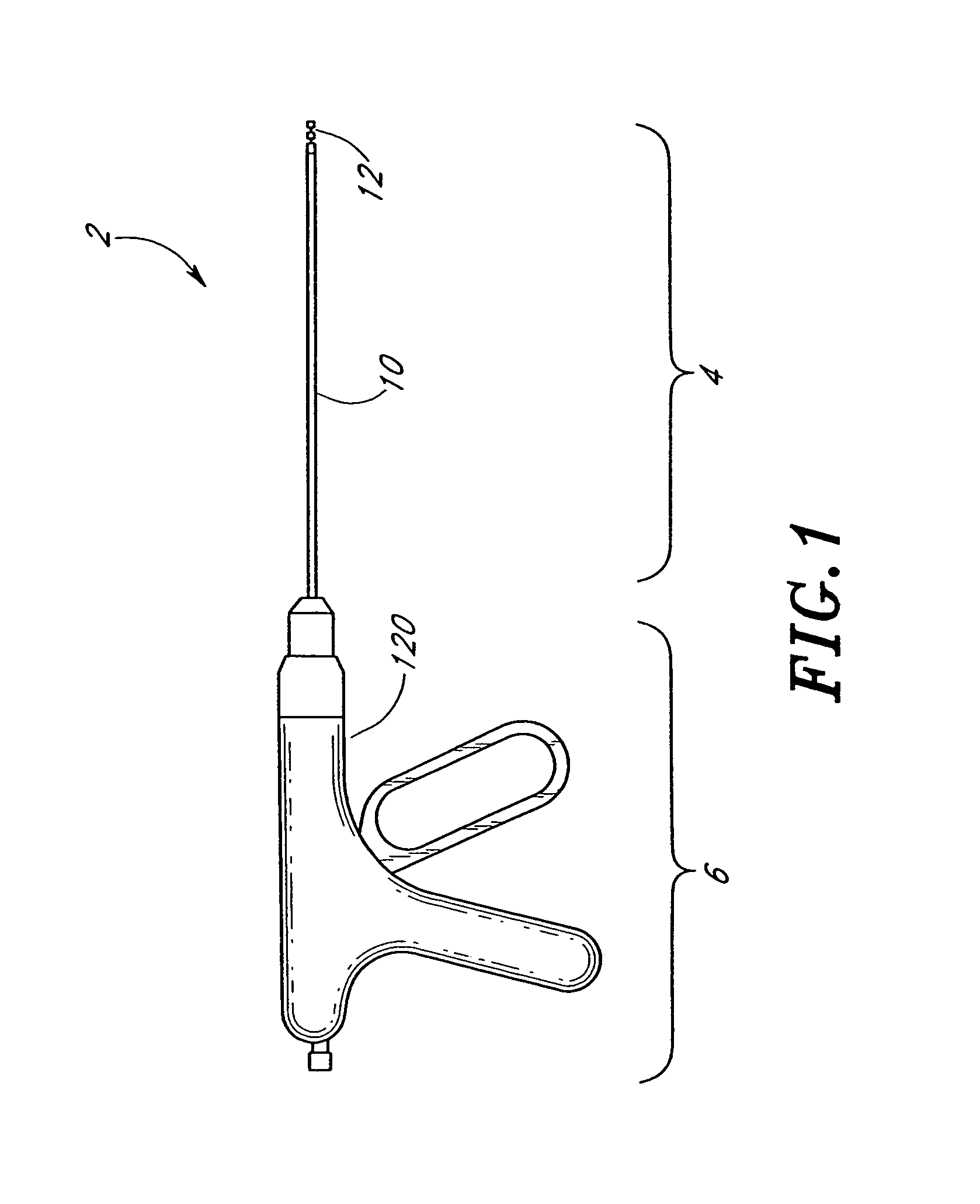
[0039]FIG. 1 illustrates a preferred embodiment of a suturing device 2 which allows a physician to suture biological tissue at a variety of locations and at a variety of depths within a body. For example, the suturing device 2 may be used to suture two layers or sections of tissue, such as an end-to-side anastomosis.

[0040]The suturing device 2 of the preferred embodiment illustrated in FIG. 1 comprises a distal portion 4 and a proximal portion 6, each extending along a common longitudinal axis. The distal portion 4 of the suturing device 2 is the portion farthest from the physician or user (i.e., closest to the suture site). The proximal portion 6 of the suturing device 2 is the portion closest to the user. In the description below, the distal direction is defined as the direction along the longitudinal axis away from the user, and the proximal direction is defined as the direction along the longitudinal axis toward the user.

[0041]The distal portion 4 of the suturing device 2 compri...


PUM


Abstract

A suturing device for suturing a portion of biological tissue includes a needle attached to a suture, a needle holder that releasably holds the needle, and a needle driver adapted to be advanced and retracted substantially parallel to a longitudinal axis of the suturing device. A distal needle holder adapted to releasably hold the needle is positioned in a distal position relative to the portion of biological tissue and a distal end of the needle driver is positioned in a proximal position relative to the portion of biological tissue. The needle is positioned in either the proximal position or the distal position. The needle driver is moved longitudinally in a first direction along a path substantially parallel to the longitudinal axis such that the needle and suture pass through the portion of biological tissue, thereby forming a suture incision through which the suture passes. By repeating the above-described processes, a series of stitches is thereby formed.

Description

[0001]This application claims priority to U.S. Provisional Patent Application No. 60 / 142,106, filed Jul. 2, 1999.BACKGROUND OF THE INVENTION[0002]1. Field of the Invention[0003]The present invention relates generally to medical devices. Specifically, the present invention relates to devices for facilitating the suturing of biological tissue.[0004]2. Description of the Related Art[0005]Sutures are frequently used to close various openings such as cuts, punctures, and incisions in various places in the human body. Because of their importance and frequent use, several types of sutures and devices for their implantation and extraction have been developed. Typically, suturing is performed by repeatedly passing a sharp suture needle attached to a length of suture material through portions of tissue to be sutured together, thereby forming loops of suture material passing through the tissue. The free ends of the suture material are then tied together to complete the suturing procedure.[0006...

Claims


Application Information

Patent Timeline
Patent Type & Authority Patents(United States)
IPC IPC(8): A61B17/04A61B17/12A61B17/06
CPCA61B17/0469A61B17/0483A61B17/0625A61B17/0491A61B2017/06028
Inventor NOBLES, ANTHONY A.PETERSON, RODDECKER, STEVENBROSH, BENJAMIN
Owner QUICKPASS
Why Eureka
Eureka Blog
Learn More