Image forming system, and information processing apparatus and method
a technology information processing apparatus, which is applied in the field of image forming system, can solve the problems of inability to consider interface features in the present image forming system, the time required for printing to complete, and the time required for decompression. large amount of time,
- Summary
- Abstract
- Description
- Claims
- Application Information
AI Technical Summary
Problems solved by technology
Method used
Image
Examples
first embodiment
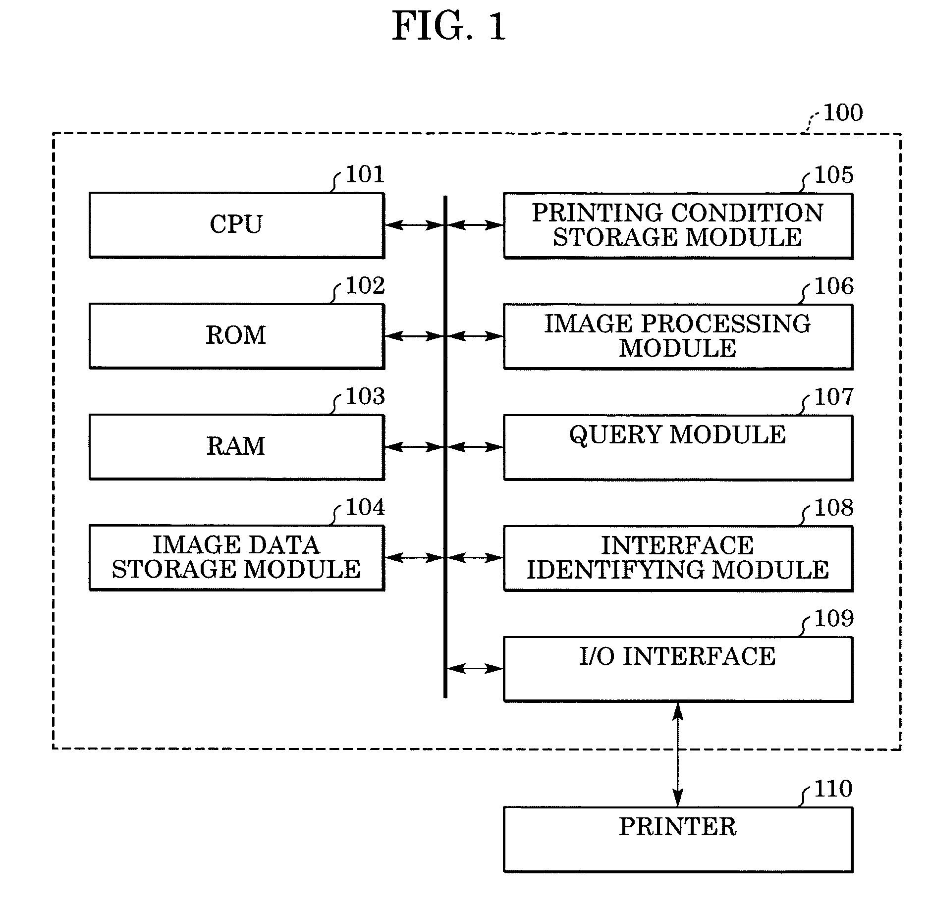
[0038]FIG. 1 shows the configuration of a printing system according to a first embodiment of the present invention. In FIG. 1, the printing system shown in FIG. 1 includes a host computer 100 and a printer 110 serving as an image forming apparatus. As the host computer 100, a multi-purpose computer or an information processing device, such as a microcomputer built in a portable apparatus or an electronic camera, can be used. The host computer 100 includes a central processing unit (CPU) 101, a read-only memory (ROM) 102, a random access memory (RAM) 103, an input / output (I / O) interface 109, an image data storage module 104, a printing condition storage module 105, an image processing module 106, a query module 107, and an interface identifying module 108. Each module may be formed either by hardware or by software.
[0039]Next, a process of the host computer 100 in the first embodiment of the present invention is described with reference to FIG. 2. This process is performed by the CPU...
second embodiment
[0053]Next, a second embodiment of the present invention is described below.
[0054]FIG. 4 shows the configuration of a printing system according to the second embodiment of the present invention. In FIG. 4, the printing system shown in FIG. 4 includes a printer 110 as an image forming apparatus and a host computer 200. Similarly to the first embodiment, a multi-purpose computer or an information processing device, such as a microcomputer built in a portable apparatus or an electronic camera, can be used as the host computer 200. The host computer 200 according to the second embodiment of the present invention includes a CPU 101, a ROM 102, a RAM 103, an I / O interface 109, an image compression module 201, an image data storage module 104, a printing condition storage module 202, an image processing module 203, a query module 204, and an interface identifying module 108. Each module may be formed either by hardware or by software.
[0055]Next, a process of the host computer 200 according...
third embodiment
[0074]Next, a third embodiment of the present invention is described below.
[0075]FIG. 7 shows the configuration of a printing system 300 according to the third embodiment of the present invention.
[0076]When the printing system 300 uses a printer 302 to print out print data, such as a document or an image, created by an application, which can be activated by a personal computer (host computer) 301 or the like, the printing system 300 quantizes the print data to a level at which it can be output by the printer 302, compresses the quantized print data, and transmits the compressed print data to the printer 302.
[0077]The configuration and operation of the printing system 300 are specifically described below.
Configuration of Printing System 300
[0078]As shown in FIG. 7, in the printing system 300, the printer 302, a hard disk 303, a display device 304, a data input device 305, a media reader 306, and a communication controller 307 are connected to the personal computer 301. By executing a...
PUM
 Abstract
Description
Claims
Application Information
 - R&D
- Intellectual Property
- Life Sciences
- Materials
- Tech Scout
- Unparalleled Data Quality
- Higher Quality Content
- 60% Fewer Hallucinations
Browse by: Latest US Patents, China's latest patents, Technical Efficacy Thesaurus, Application Domain, Technology Topic, Popular Technical Reports.
© 2025 PatSnap. All rights reserved.Legal|Privacy policy|Modern Slavery Act Transparency Statement|Sitemap|About US| Contact US: help@patsnap.com


