
Liquid crystal display apparatus with phase difference layers

a phase difference layer and display apparatus technology, applied in the field of liquid crystal display apparatus, can solve the problems of deteriorating contrast ratio in the front direction, difficult to uniformly retard the in-plane retardation, and deteriorating display quality, so as to prevent deterioration of contrast ratio and wide angle of view

Inactive Publication Date: 2009-08-18
SHARP KK
View PDF15 Cites 6 Cited by
  • Summary
  • Abstract
  • Description
  • Claims
  • Application Information

AI Technical Summary

Benefits of technology

[0009]The present invention has an object to offer an LCD with an ability to maintain a broad angle of visibility without losing a balance between viewing angle characteristics from an above position (or a bottom position) and those from a right position (or a left position), and further having an ability to prevent a deterioration of contrast ratio in a front direction.

Problems solved by technology

For instance, a liquid crystal display apparatus (an LCD), which is used as a display screen in a notebook-sized personal computer or a word processor, has a tendency to have a deteriorated display quality when it is viewed from a diagonal direction, because its optical anisotropy gives the LCD a narrower angle of visibility, compared to other display apparatus, such as CRT.
Thus, it is a problem for the above arrangement that it is difficult to uniform their in-plane retardation.
Here, if a difference is caused between their retardations, for example, by lack of uniformity between their respective manufacturing processes, a light leakage in a front direction is generated during the black display, thus deteriorating a contrast ratio in a front direction.
Furthermore, in the above arrangement, when a contrast ratio of a predetermined angle from the normal direction is measured for every in-plane directions, a peak of the contrast ratio often shows unevenness, thus making it hard to balance between viewing angle characteristics from an above position (or a bottom position) and those from a right position (or a left position).

Method used


Image

  • Liquid crystal display apparatus with phase difference layers
  • Liquid crystal display apparatus with phase difference layers
  • Liquid crystal display apparatus with phase difference layers

Examples


first embodiment

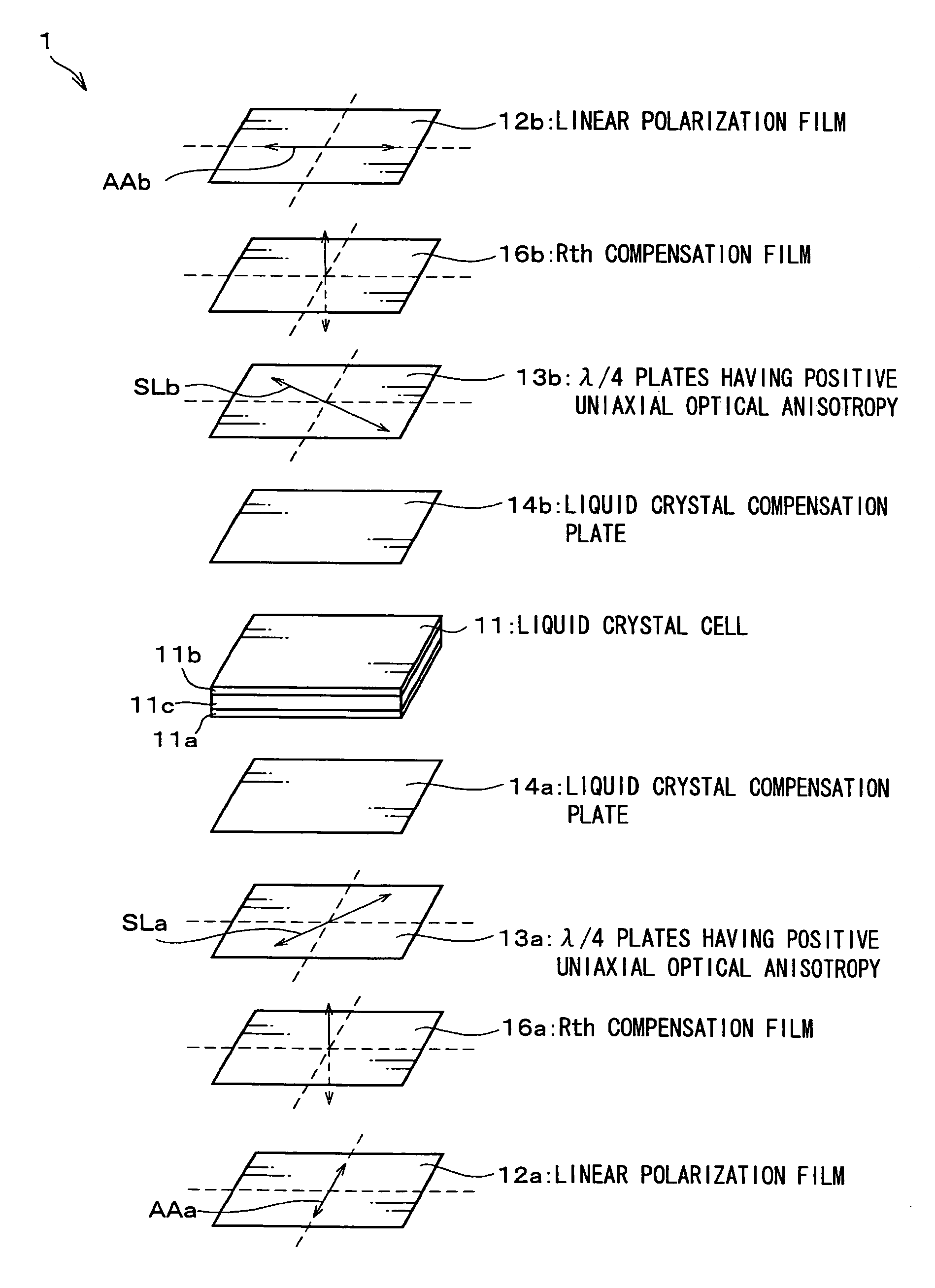
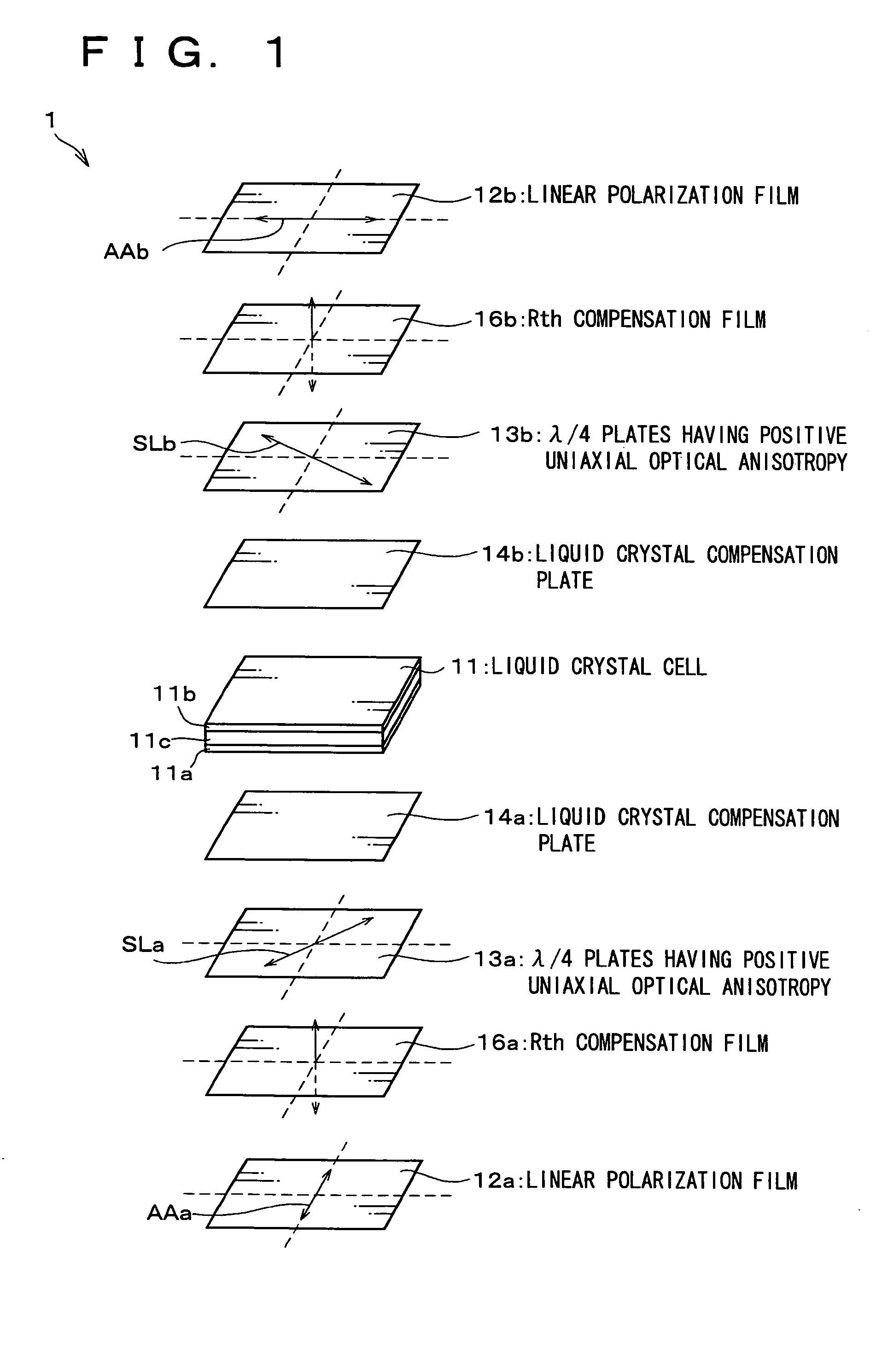
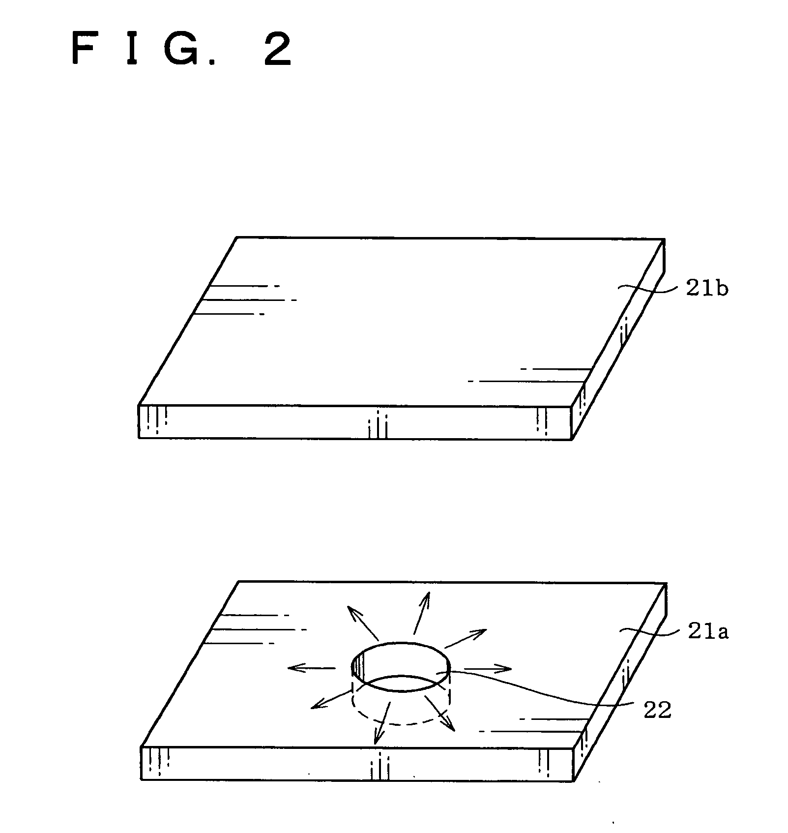
[0067]Explained below is a first embodiment of the present invention, with reference to FIGS. 1 to 16 and 43. It should be noted that, the present invention can be employed for liquid crystal cells of other types, as it will be explained later, but described below is a liquid crystal cell, in which liquid crystal molecules have different alignment directions from each other in a pixel, for example, radiate and inclined alignment (that is, the alignment is in a radiated manner in terms of in-plane directions and is inclined with respect to the perpendicular direction) or multi domain alignment, as a suitable example.

[0068]An LCD 1 of the present embodiment, as shown in FIG. 1, including a liquid crystal cell 11, linear polarization films (polarizers) 12a and 12b which are disposed on both sides of the liquid crystal cell 11, is characterized by having the following arrangement, namely: the liquid crystal cell 11 is provided with a TFT substrate 11a (a first substrate), an opposite su...

second embodiment

[0130]An LCD 1c of the present embodiment, as shown in FIG. 17, in addition to the arrangement shown in FIG. 1, a polarization plate compensation film (polarizer compensation layer) 15a (15b) is provided between a linear polarization film 12a (12b) and a λ / 4 plate 13a (13b). The polarization plate compensation film 15a (15b) has a lag phase axis to cross with an absorption axis AAa (AAb) of the linear polarization film 12a (12b). The polarization plate compensation film 15a (15b) has a retardation in a perpendicular direction opposite to that of the Rth compensation films 16a and 16b, just like the case of supports for the linear polarization films 12a and 12b, and the λ / 4 plates 13a and 13b. The retardations in the perpendicular of the Rth compensation films 16a and 16b are set to cancel out the retardation in the perpendicular direction of the supports, the polarization plate compensation film 15a (15b) as well as that of the λ / 4 plate 13a (13b).

[0131]Specifically, the polarizatio...

third embodiment

[0137]By the way, in the arrangements shown in FIG. 1 and FIG. 2, the Rth compensation films 16a and 16b are provided for making the retardation Rth1 in the perpendicular direction substantially zero. But, in a present embodiment, explained is a case where a λ / 4 plate 13a (13b) having a small retardation in a perpendicular direction is used, without providing the Rth compensation films 16a and 16b.

[0138]As shown in FIG. 20, an LCD 1d of the present embodiment has an arrangement which is identical with that shown in FIG. 1, except the Rth compensation films 16a and 16b are omitted and the λ / 4 plate 13a (13b) is replaced with a film whose characteristics can be described by a biaxial refraction ellipsoid that satisfies (nx+ny) / 2=nz.

[0139]Here, let d be thickness, where the retardation Rth in the perpendicular direction can be described by an equation Rth=d·{nz−(nx+ny) / 2}, the retardation in the perpendicular direction of the film is 0 nm. On the other hand, because a retardation Re i...


PUM

PropertyMeasurementUnit
wavelengthaaaaaaaaaa
polar angleaaaaaaaaaa

Abstract

A liquid crystal display apparatus, provided with liquid crystal compensation plates and λ / 4 plates on both sides of a liquid crystal cell, in a sequence that the liquid crystal compensation plates, then the λ / 4 plates. Further provided is Rth compensation film between the λ / 4 plate and linear polarization film. Set substantially at zero is a retardation Rth1 in a perpendicular direction in a range from the linear polarization films to the λ / 4 plates, excluding the λ / 4 plates. This gives a retardation (in a perpendicular direction) for optically compensating the liquid crystal cell a closer position to the liquid crystal cell. As a result, a broad angle of visibility can be maintained, without losing a balance between viewing angle characteristics from the above position (or the bottom position) and those from the right position (or the left position), while it is possible to prevent contrast ratio in a front direction from being lowered. Therefore, an LCD having good display quality can be realized.

Description

[0001]This application is a divisional of U.S. patent application Ser. No. 09 / 866,797, filed on May 30, 2001 now U.S. Pat. No. 6,922,222, which claims priority of JP application No. 2000-163236 filed 31 May 2000 and JP application No. 2001-133547 filed 27 Apr. 2001. The entire contents of these applications are incorporated herein by reference.FIELD OF THE INVENTION[0002]The present invention relates to a liquid crystal display apparatus provided with a polarizer and a quarter wavelength layer.BACKGROUND OF THE INVENTION[0003]For instance, a liquid crystal display apparatus (an LCD), which is used as a display screen in a notebook-sized personal computer or a word processor, has a tendency to have a deteriorated display quality when it is viewed from a diagonal direction, because its optical anisotropy gives the LCD a narrower angle of visibility, compared to other display apparatus, such as CRT. Hence, for example, an LCD 501 described in Japanese Un-Examined Patent Publication Tok...

Claims


Application Information

Patent Timeline
Patent Type & Authority Patents(United States)
IPC IPC(8): G02F1/1335G02B5/30G02F1/13363G02F1/1337G02F1/139
CPCG02F1/133634G02F2001/133638G02F1/133638G02F1/13363
Inventor MIYACHI, KOICHIYAMAHARA, MOTOHIRO
Owner SHARP KK
Learn More