
Connectorized fiber optic cabling and methods for forming the same

a technology of connecting fiber optic cabling and fiber optic cables, applied in the field of communication cabling, can solve the problems of various drawbacks in cost, bendability, bendability, etc., and achieve the effects of reducing the cost of installation

Active Publication Date: 2009-05-26
COMMSCOPE INC
View PDF55 Cites 56 Cited by
  • Summary
  • Abstract
  • Description
  • Claims
  • Application Information

AI Technical Summary

Benefits of technology

This solution improves bendability and reduces costs by eliminating the need for furcation tubing, while maintaining the benefits of round, loose tube cabling, and preventing fiber breaks and performance losses during bending.

Problems solved by technology

However, ribbonized cabling may suffer from drawbacks in bendability and cost.
This method using furcation tubing may suffer from various drawbacks in cost, bendability, installation requirements, etc.

Method used


Image

  • Connectorized fiber optic cabling and methods for forming the same
  • Connectorized fiber optic cabling and methods for forming the same
  • Connectorized fiber optic cabling and methods for forming the same

Examples


Embodiment Construction

[0018]The present invention now will be described more fully hereinafter with reference to the accompanying drawings, in which illustrative embodiments of the invention are shown. In the drawings, the relative sizes of regions or features may be exaggerated for clarity. This invention may, however, be embodied in many different forms and should not be construed as limited to the embodiments set forth herein; rather, these embodiments are provided so that this disclosure will be thorough and complete, and will fully convey the scope of the invention to those skilled in the art.

[0019]It will be understood that when an element is referred to as being “coupled” or “connected” to another element, it can be directly coupled or connected to the other element or intervening elements may also be present. In contrast, when an element is referred to as being “directly coupled” or “directly connected” to another element, there are no intervening elements present.

[0020]In addition, spatially rel...


PUM


Abstract

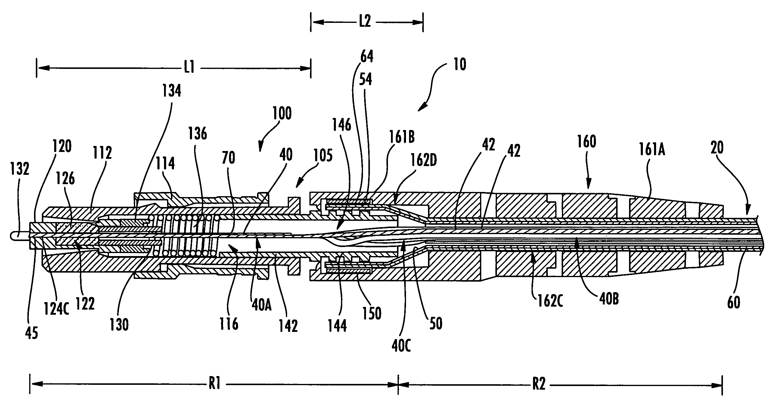
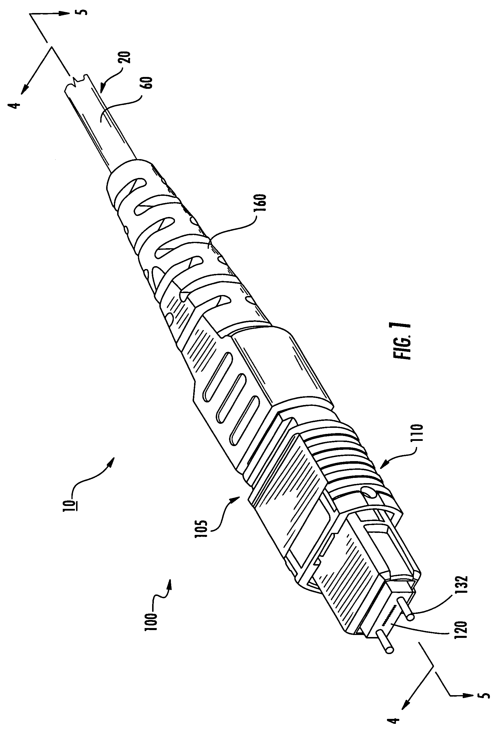
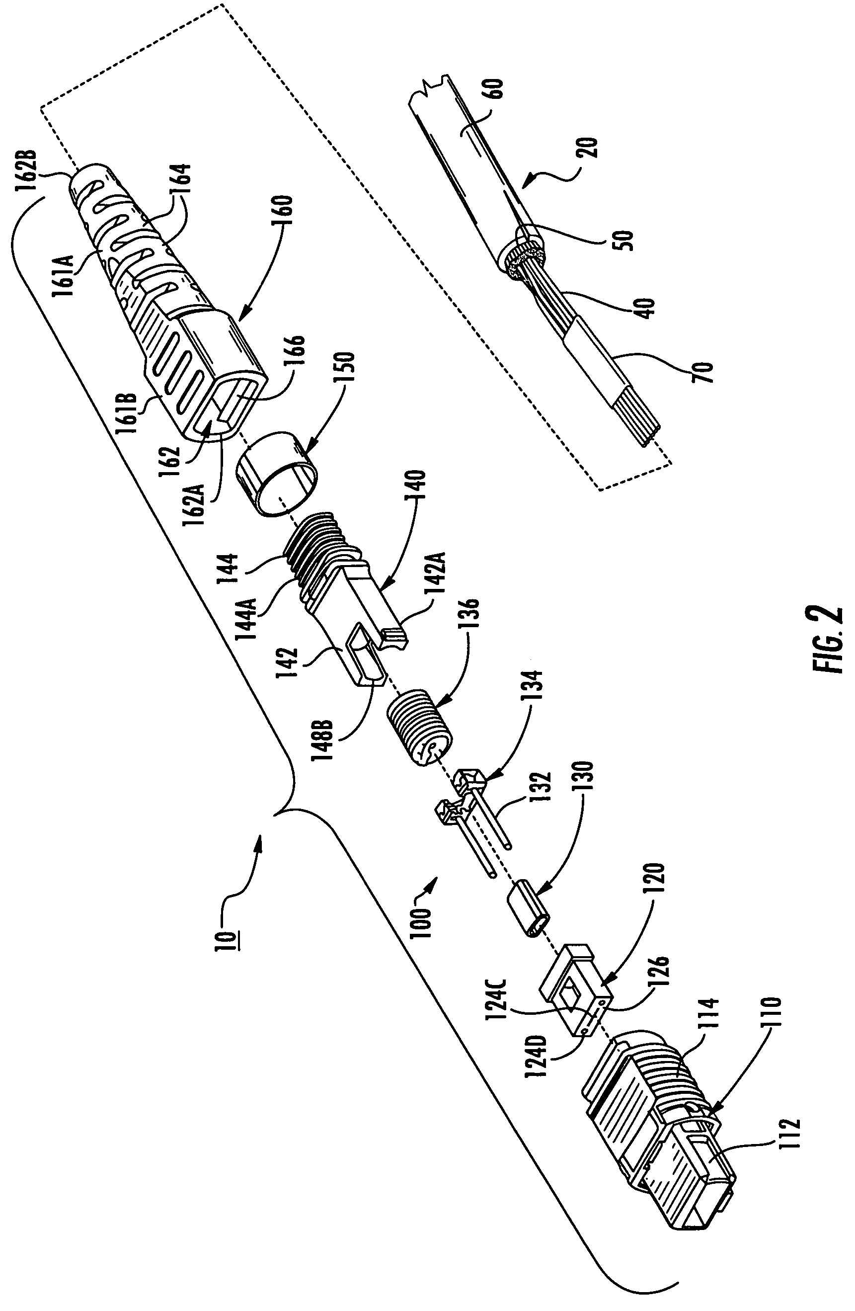
A connectorized fiber optic cabling assembly includes a loose tube fiber optic cable and a connector assembly. The cable has a termination end and includes: an optical fiber bundle including a plurality of optical fibers; at least one strength member; and a jacket surrounding the optical fiber bundle and the at least one strength member. The connector assembly includes a rigid portion and defines a fiber passage. The connector assembly is mounted on the termination end of the cable such that the optical fiber bundle extends through at least a portion of the fiber passage. The plurality of optical fibers of the optical fiber bundle have a ribbonized configuration in the rigid portion of the connector assembly and a loose, non-ribbonized configuration outside the rigid portion. The plurality of optical fibers undergo a transition from the ribbonized configuration to the loose, non-ribbonized configuration in the rigid portion of the connector assembly. According to some embodiments, the rigid portion of the connector assembly includes a rigid connector housing.

Description

RELATED APPLICATIONS[0001]This application claims the benefit of priority from U.S. Provisional Patent Application No. 60 / 688,492, filed Jun. 8, 2005, and U.S. Provisional Patent Application No. 60 / 688,493, filed Jun. 8, 2005, the disclosures of which are incorporated herein by reference in their entireties.FIELD OF THE INVENTION[0002]The present invention relates to communications cabling and, more particularly, to connectorized fiber optic cabling and methods for forming the same.BACKGROUND OF THE INVENTION[0003]Fiber array connectors are commonly employed to terminate multi-fiber fiber optic cables. Such connectors require that the fibers of the cable be arranged in a row or side-by-side, aligned configuration. In some cases, multiple, stacked layers or rows of fibers may be used. One method for providing fibers so arranged is to use ribbonized cabling. However, ribbonized cabling may suffer from drawbacks in bendability and cost. Another method is to use loose tube fiber cabling...

Claims


Application Information

Patent Timeline
Patent Type & Authority Patents(United States)
IPC IPC(8): G02B6/40
CPCG02B6/3885G02B6/3887G02B6/3888G02B6/38875
Inventor ANDERSON, TIMOTHY W.CASE, RICHARD L.
Owner COMMSCOPE INC
Learn More