Eureka AIR delivers breakthrough ideas for toughest innovation challenges, trusted by R&D personnel around the world.

Apparatus for stripping fibre material from textile fibre bales of spinning material, for example cotton, synthetic fibres and the like

a technology of textile fibre bales and aprons, which is applied in the direction of mechanical treatment, carding machines, textiles and paper, etc., can solve the problem of not being able to ascertain the exact location of the carriage, and achieve the effect of reducing the loss of scattered light, simple mounting of optical distance sensors, and free from wear

Inactive Publication Date: 2009-03-24
TRUETZSCHLER GMBH & CO KG
View PDF14 Cites 8 Cited by
  • Summary
  • Abstract
  • Description
  • Claims
  • Application Information

AI Technical Summary

Benefits of technology

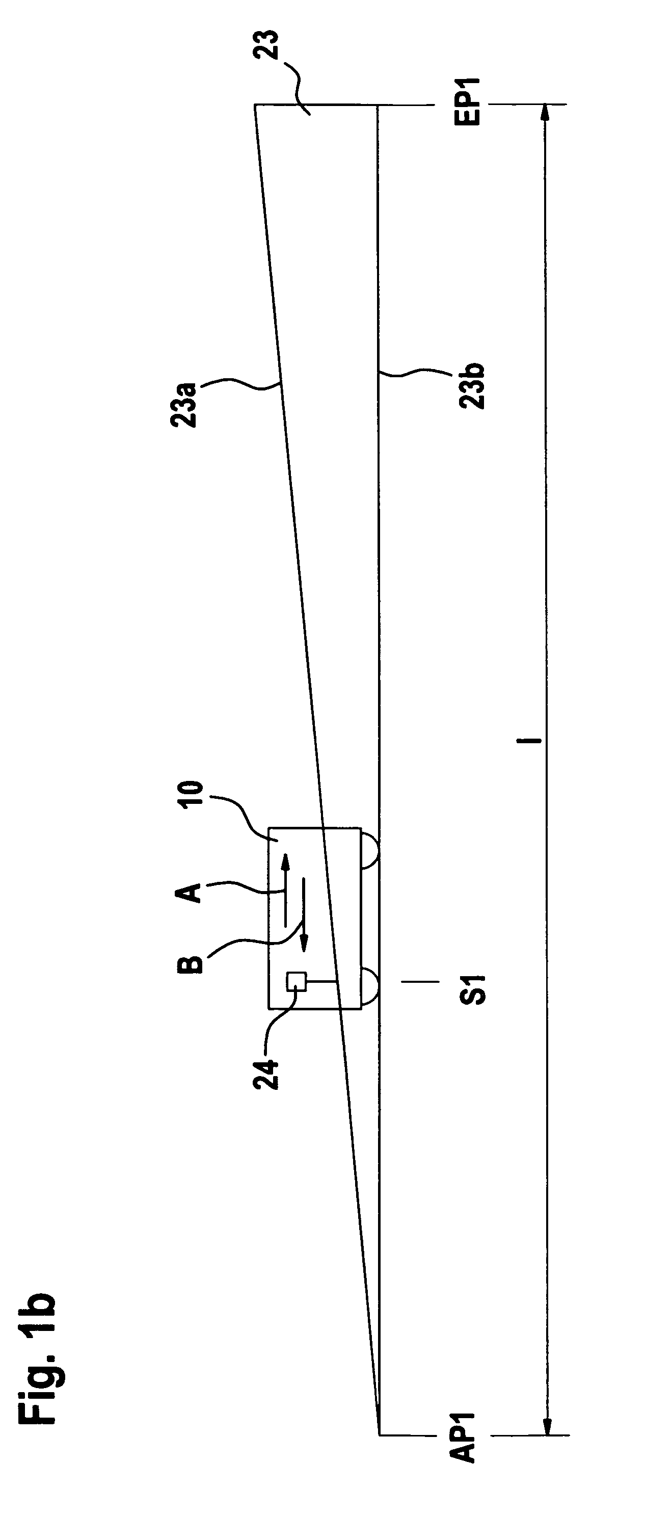
[0009]As a result of the fact that an optical distance sensor scans a counter-surface, especially a sloping surface, for example a ramp or the like, large distances are calculated very exactly by means of relatively small distance measurements. It is especially advantageous that for measurement of just small distances economically priced distance sensors can be used. In addition, distance measurement performed over a short distance is more exact (focussed) because scattered light losses are minimised. Mounting of the optical distance sensors is simple. Overall, position detection (location determination) that is maintenance-free and free from wear is made possible. Irrespective of the position and the work region in which the machine is located, the control (evaluation device) calculates the position (location) of the lower carriage or removal device immediately after the machine has been switched on. Finally, no slippage is present.

Problems solved by technology

Using those sensors it is not possible to ascertain the location of the carriage exactly.
In addition, it is disadvantageous that the sensors have to act over a relatively large distance in the horizontal direction in order that the travel speed of the heavy machine resulting from the substantial weight of the carriage and the tower together with the boom, for example 2.8 tonnes, can be reliably slowed down in good time without damage.

Method used


Image

  • Apparatus for stripping fibre material from textile fibre bales of spinning material, for example cotton, synthetic fibres and the like
  • Apparatus for stripping fibre material from textile fibre bales of spinning material, for example cotton, synthetic fibres and the like
  • Apparatus for stripping fibre material from textile fibre bales of spinning material, for example cotton, synthetic fibres and the like

Examples


Embodiment Construction

[0027]With reference to FIGS. 1a and 2a, an apparatus 1 for stripping fibre tufts, for example a bale opener known as BLENDOMAT BDT 019 (Trade Mark), made by Trutzschler GmbH & Co. KG of Monchengladbach, Germany, has a tower 2 on a carriage 10, which travels to and fro in the direction of arrows A, B parallel to a row of bales 3. On one side of the tower 2, a laterally cantilevered take-off element 4 is connected to the tower 2. The take-off element 4 comprises two take-off rollers 5, 6 (high-speed stripping rollers) that rotate in opposite directions. The take-off element 4 is mounted on the movable tower 2 by way of a holding device 7. The fibre tufts taken off by the stripping rollers 5, 6 are drawn off under suction through a material removal port 8 and a suction line 9, which co-operates with a suction duct 11. The surface of the row of bales 3 is stripped horizontally. The take-off element 4 having the associated stripping device is mounted on the tower 2 so as to be movable i...


PUM

PropertyMeasurementUnit
angleaaaaaaaaaa
heightaaaaaaaaaa
lengthaaaaaaaaaa

Abstract

An apparatus for stripping fiber material from textile fiber bales has a tower, which can be moved to and fro in relation to the fiber material by means of a carriage having a travel motor or the like, and has at least one boom, which is provided with the stripping apparatus. The boom together with the stripping apparatus can be moved in the height direction of the tower by means of a lifting motor or the like. A movable distance sensor is provided for determination of the location in the length direction. In order to make possible, by simple means, an exact determination of location in the length and / or height direction, a movable distance sensor scans, for location determination in the length and / or height direction, the distances to a counterpart element and calculates from those distances the location.

Description

CROSS REFERENCE TO RELATED APPLICATION[0001]This application claims priority from German Patent Application No, 10 2005 013 076.3 dated Mar. 18, 2005, the entire disclosure of which is incorporated herein by reference.BACKGROUND OF THE INVENTION[0002]The invention relates to an apparatus for taking-off fibre material from textile fibre bales of spinning material, for example cotton, synthetic fibres and the like, by means of a stripping apparatus or the like, wherein a tower, which can be moved to and fro in relation to the fibre material by means of a carriage, which has a travel motor or the like, has at least one boom, which is provided with the stripping apparatus and which extends in a transverse direction to the direction of movement, and the boom together with the take-off apparatus can be moved in the height direction of the tower by means of a lifting motor or the like.[0003]In a known apparatus (DE-A- 37 22 317), the take-off apparatus is provided with sensors which regist...

Claims


Application Information

Patent Timeline
Patent Type & Authority Patents(United States)
IPC IPC(8): D01G15/40D01G7/04
CPCD01G7/06
Inventor MINTER, FRANZ-JOSEF
Owner TRUETZSCHLER GMBH & CO KG
Why Eureka
Eureka Blog
Learn More