
Bolt assembly for the attachment of toilet seats and other articles

a technology for toilet seats and other objects, applied in the field of bolt assemblies, can solve the problems of difficult removal, cumbersome removal of toilet seat assemblies for cleaning, and usually only removing seat assemblies

Inactive Publication Date: 2009-02-17
RICHTER MILTON
View PDF18 Cites 10 Cited by
  • Summary
  • Abstract
  • Description
  • Claims
  • Application Information

AI Technical Summary

Benefits of technology

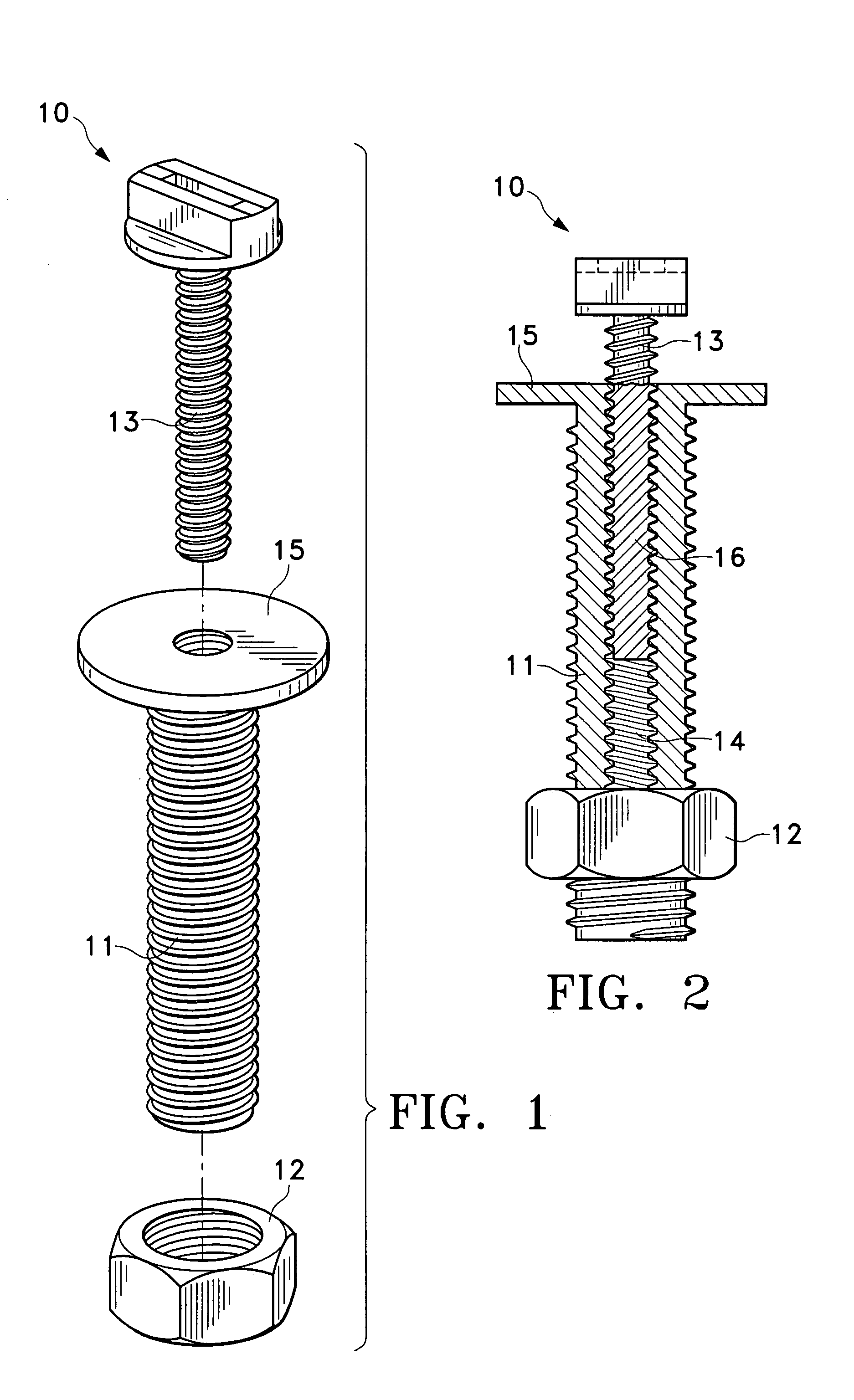
[0007]The present invention provides a simple three piece bolt assembly that can be used to reversibly fasten a toilet seat assembly to the flange of a toilet bowl. This assembly can also be used to securely and reversibly connect a variety of other two part systems.
[0008]It is an object of the present invention to provide a bolt assembly that can be used with toilet seats currently on the market and in use.

Problems solved by technology

This type of installation has always made removal of the toilet seat assembly for cleaning a cumbersome task.
The result has been that the seat assembly is usually only removed when there is a need to change it.
Additionally, after remaining in place for a considerable period of time, the nuts and bolts that maintain the seat assembly in place are often badly corroded making removal very difficult, and more so when it is necessary to reach under the flange or get down beneath the flange to perform this task.
After time the connections can become worn and loose so that the seat assembly will no longer be held securely in place.
Repeated removal and replacement can cause damage to the pin or cause wear within the hollow so that over time, the fit will not remain tight.
This bolt assembly is designed to be used with a complementing seat assembly and cannot be used with other existing systems.
The parts are made of a plastic material and the snap fit can wear and become loose after repeated removals.

Method used


Image

  • Bolt assembly for the attachment of toilet seats and other articles
  • Bolt assembly for the attachment of toilet seats and other articles
  • Bolt assembly for the attachment of toilet seats and other articles

Examples


Embodiment Construction

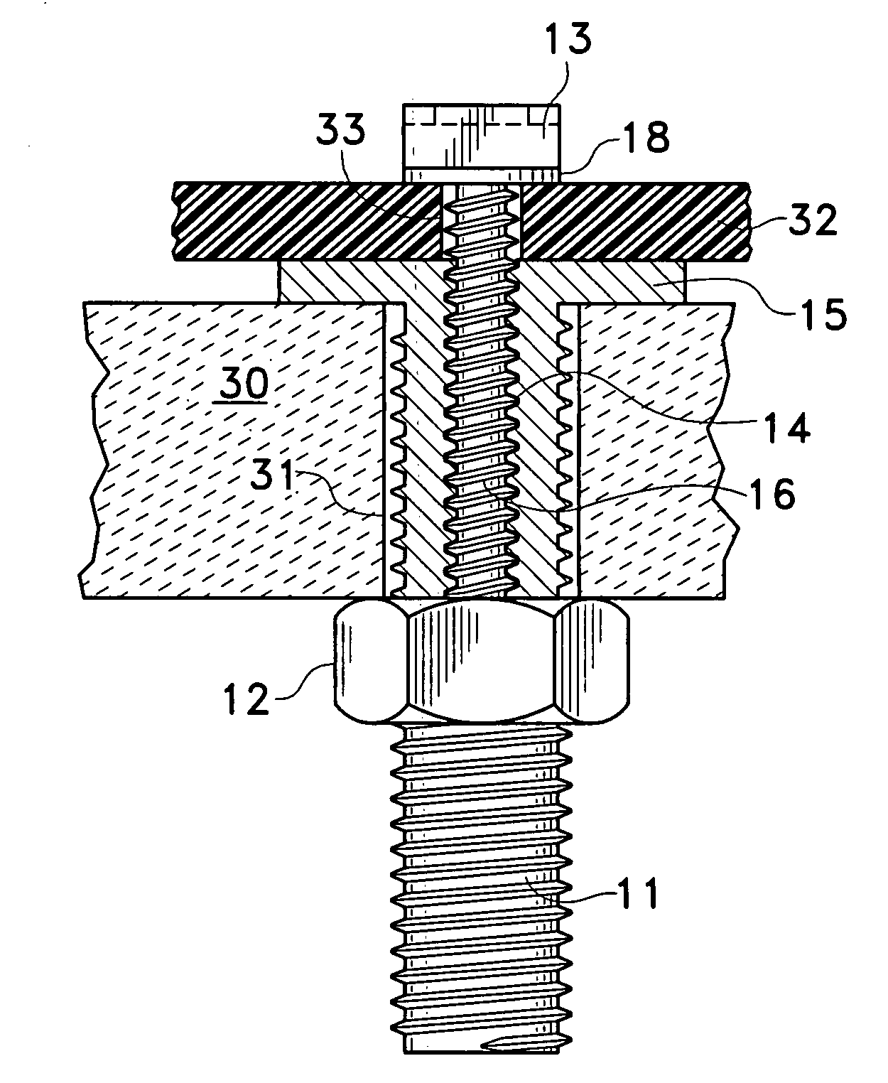
[0026]The bolt assembly 10 of the present invention may be designed to enable rapid and easy reversible removal of the toilet seat for cleaning. The bolt assembly 10 may be used with any conventional toilet bowl having a rear flange with two vertical cylindrical openings therethrough. The design may insure compatibility with toilet fixtures having flanges of different thickness. The initial step in attaching the toilet seat may require minimal access below the flange, but subsequent removal and replacement of the seat may be accomplished entirely from above the flange.

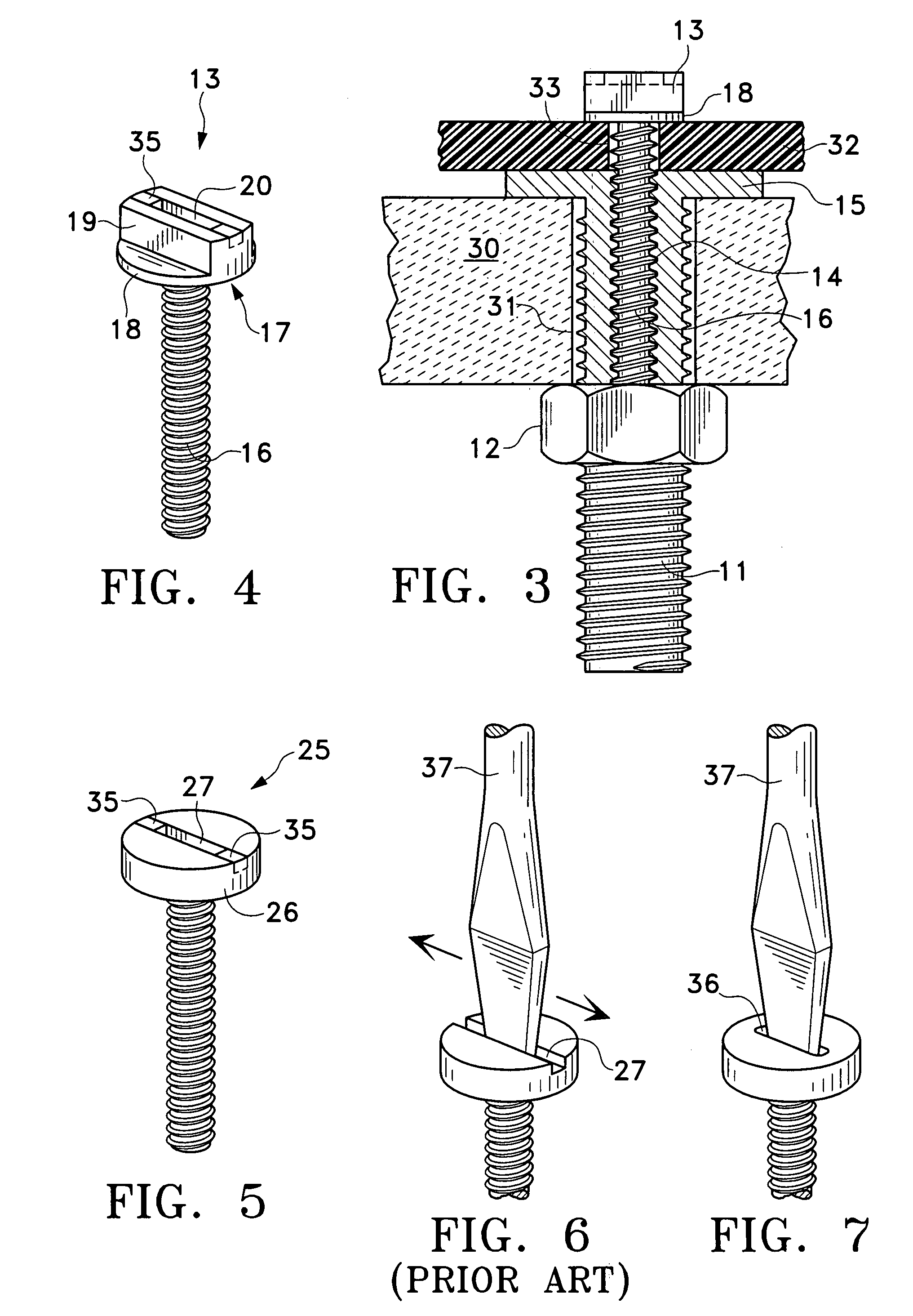
[0027]The bolt assembly 10 may consist of three components as seen in FIGS. 1 and 2, a bolt 11, a nut 12 and a screw 13. The bolt 11 may be threaded on its exterior surface and may have a threaded bore 14 extending axially along its full length. There may be a collar 15 about the upper end of the bolt 11. The collar 15 may be sufficiently larger in diameter than the opening in the flange of the toilet bowl so the bolt ...


PUM


Abstract

A bolt assembly for use with toilet seats and other objects consists of a threaded bolt with a threaded axial bore and a head larger than the opening in the toilet bowl flange, a nut sized to fit the bolt, and a screw dimensioned to cooperate with the bore. The bolt is inserted through the opening in the flange, extending there beyond. The bolt is secured from below the flange with the nut. The seat assembly is then placed on the flange so that the aperture in the seat assembly bracket communicates with the threaded bore. The seat assembly is secured in place by passing the screw through the aperture in the bracket and threading it into the bore. The seat assembly can then be reversibly removed for cleaning by merely removing and replacing the screw without having to reach under the flange. The screw can have a gripping head so that it can be rotated without the need for a screwdriver, or there can be a slot centered on the top of the head so that a screwdriver can be used. The slot can be sized to accept a screwdriver but such that it will not permit the screwdriver to slip sideways during use.

Description

FIELD OF THE INVENTION[0001]The instant invention relates to bolt assemblies for the secure attachment of a toilet seat assembly to the toilet bowl flange while enabling the seat portion to be easily and reversibly removed for cleaning without having to reach under the flange.BACKGROUND OF THE INVENTION[0002]The common toilet seat assembly has been known for over a century. The installation of the toilet seat assembly has always required the installer to maneuver under the back end or flange of the toilet bowl to reach the attaching bolt and fasten the nut. This type of installation has always made removal of the toilet seat assembly for cleaning a cumbersome task. The result has been that the seat assembly is usually only removed when there is a need to change it. Additionally, after remaining in place for a considerable period of time, the nuts and bolts that maintain the seat assembly in place are often badly corroded making removal very difficult, and more so when it is necessar...

Claims


Application Information

Patent Timeline
Patent Type & Authority Patents(United States)
IPC IPC(8): A47K13/12
CPCA47K13/26
Inventor RICHTER, MILTON
Owner RICHTER MILTON
Learn More