
Electronic camera

a technology of electronic cameras and shutters, applied in the field of electronic cameras, can solve the problems of stress on the person, difficulty in releasing the shutter at the right moment, and the general suited photographing mode of still images to take a moving picture, and achieve the effect of reducing the release time lag

Inactive Publication Date: 2009-02-10
NIKON CORP
View PDF15 Cites 2 Cited by
  • Summary
  • Abstract
  • Description
  • Claims
  • Application Information

AI Technical Summary

Benefits of technology

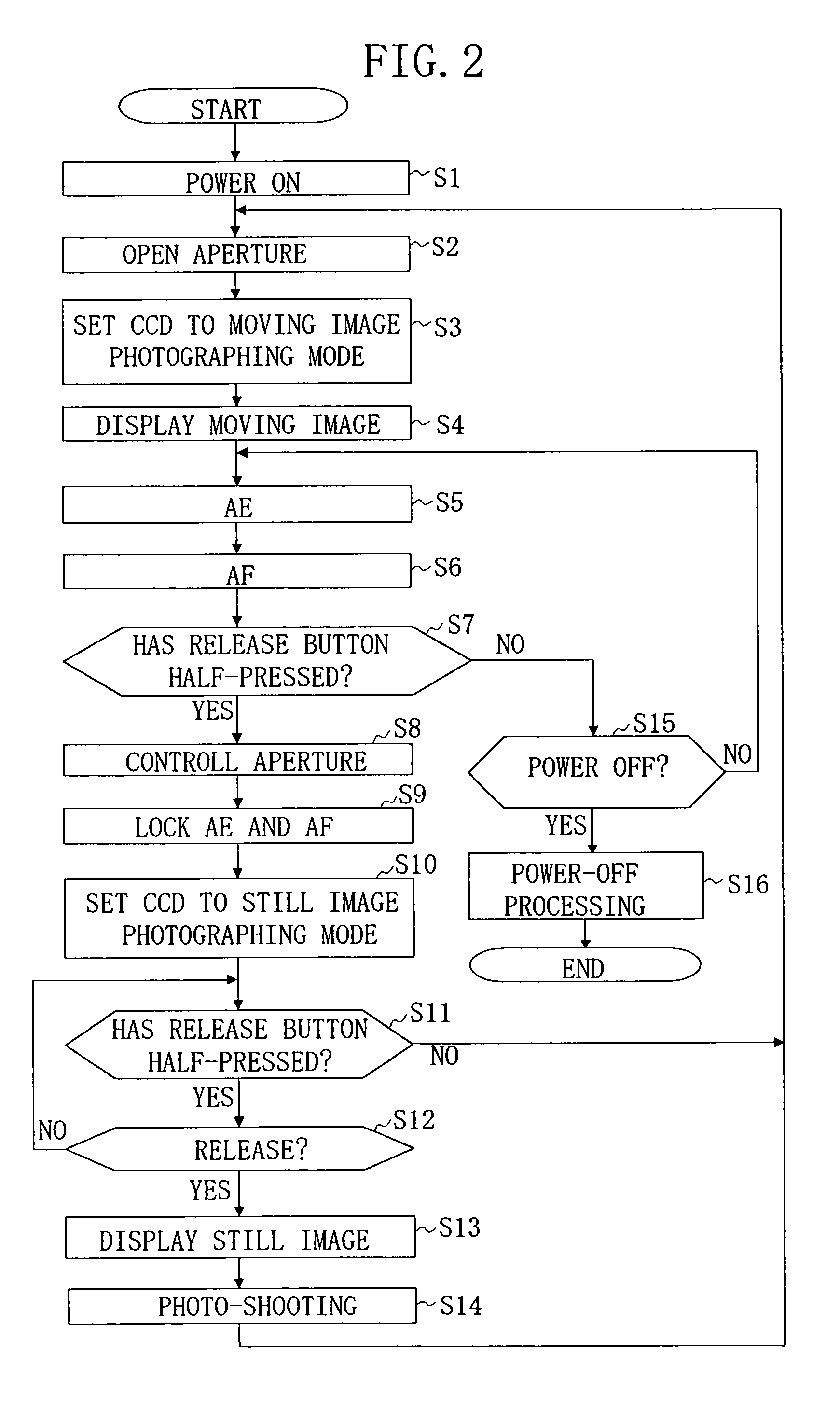
The present invention relates to an electronic camera with a function of displaying an object as a moving image. The technical effects of the invention include reducing the release time lag, improving the image quality, and preventing the occurrence of blooming. The camera has a release section that can switch between a standby mode, a preparation mode, and a shooting mode. The image pickup section is set to an appropriate mode for moving-image photographing when the release section is in the standby mode. The camera also has a display section for displaying the image data generated by the image pickup section. The release section has a release button that can switch between the preparation mode and the shooting mode. The image pickup section includes an image sensor with a plurality of photoelectric conversion elements and a plurality of charge transfer electrodes. The appropriate mode for moving-image photographing is controlled by the control of electric potential differences within the image sensor. The appropriate mode for still-image photographing is controlled by adjusting the aperture of the lens in accordance with the amount of light received from the object. These technical effects make the electronic camera more user-friendly and efficient for capturing moving images.

Problems solved by technology

Therefore, the still-image photographing mode is not generally suited to taking a moving picture.
Contrarily, longer release time lag may cause difficulty releasing the shutter at the right moment and stress on the person who takes a photo.

Method used


Image

  • Electronic camera
  • Electronic camera
  • Electronic camera

Examples


Embodiment Construction

[0032]Embodiments of the invention will now be described with reference to the drawings.

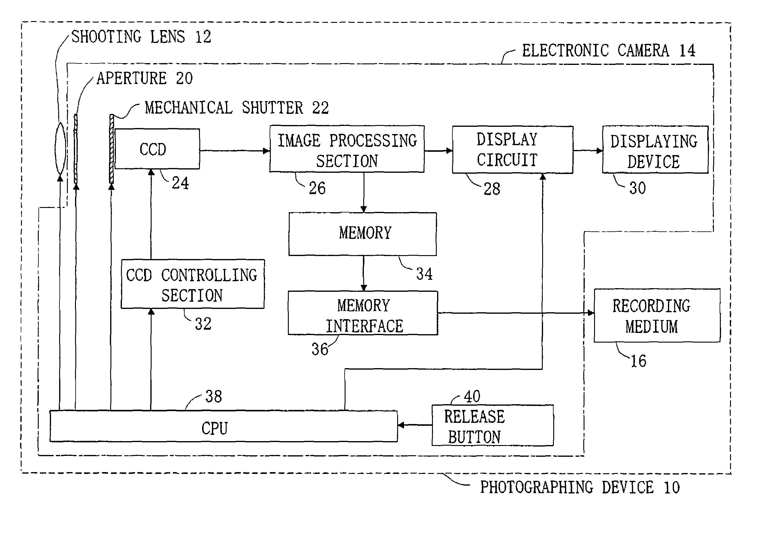
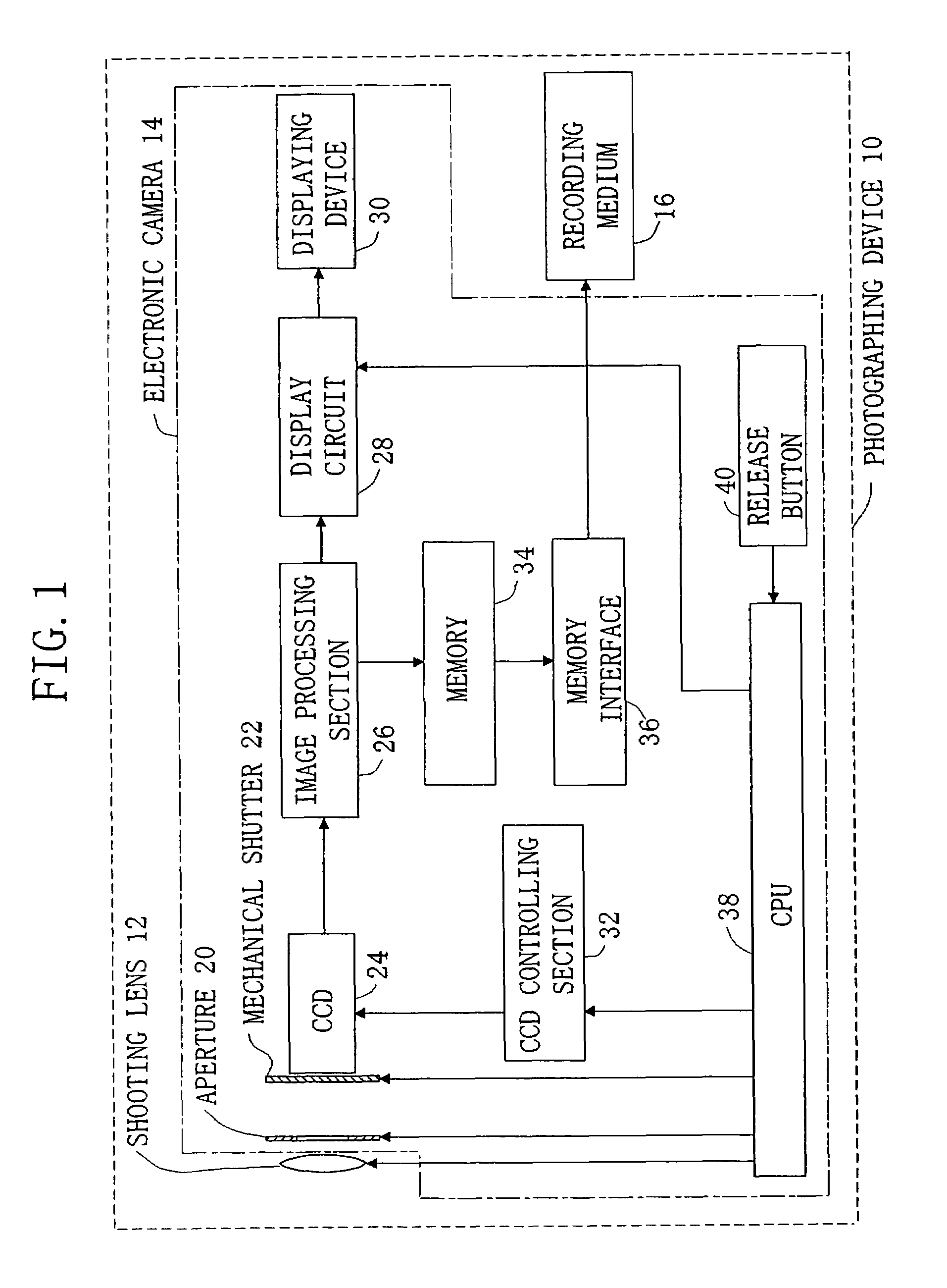
[0033]FIG. 1 is a block diagram showing the structure of a photographing device according to the present embodiment. The photographing device 10 is configured by connecting a recording medium 16 to an electronic camera 14 of the invention to which a shooting lens 12 is fixed. The electronic camera 14 includes an aperture 20, a mechanical shutter 22, a CCD 24 (image sensor), an image processing section 26, a display circuit 28, a displaying device 30, a CCD controlling section 32, a memory 34, a memory interface 36, a CPU 38, and a release button 40.

[0034]The CCD 24 includes a large number of photoelectric conversion elements and a large number of charge transfer electrodes both formed on a semiconductor substrate (not shown). The CCD 24 has a substrate voltage controlling terminal (not shown) that can make a switch between a moving-image photographing mode and a still-image photographing mode.

[00...


PUM


Abstract

An electronic camera includes a release section which, by receiving user operation, is switched from a standby mode to a preparation mode and instructs an image pickup section to prepare for shooting, and is switched from the preparation mode to a shooting mode and instructs the image pickup section to start shooting. A shooting mode controlling section sets the image pickup section to an appropriate mode for moving image photographing when the release section is in the standby mode, and sets the image pickup section to an appropriate mode for still image photographing when the release section is in the preparation mode and before the release section is switched to the shooting mode. Accordingly, since the image pickup section has already been set to the appropriate mode for still image photographing when the user operates the release section to start shooting, the release time lag can be shortened.

Description

CROSS-REFERENCE TO RELATED APPLICATIONS[0001]This application is based upon and claims the benefit of priority from Japanese Patent Application No. 2002-154006, filed on May 28, 2002, the entire contents of which are incorporated herein by reference.TECHNICAL FIELD[0002]The present invention relates to an electronic camera that photographs an object to generate image data and records the generated image data in a recording medium. The present invention also relates to an electric camera having a function of displaying an object as a moving image.BACKGROUND ART[0003]Conventional electronic cameras are known in which the light from an object is converted into electrical signals by an image sensor including a CCD (charge coupled device) and the electrical signals are converted into digital data to be recorded into a recording medium such as a flash memory and the like. Generally, the electronic camera has a color LCD (liquid crystal display) on its rear part. An object to be photograph...

Claims


Application Information

Patent Timeline
Patent Type & Authority Patents(United States)
IPC IPC(8): H04N5/225H04N1/00H04N25/00H04N101/00
CPCH04N1/00H04N5/23245H04N5/23293H04N2101/00H04N23/65H04N23/667H04N23/63
Inventor YOKONUMA, NORIKAZU
Owner NIKON CORP
Learn More