
Pressure sensor

a technology of pressure sensor and pressure sensor, which is applied in the direction of fluid pressure measurement, variable capacitor, instruments, etc., can solve the problems of inability to produce a big drilling at a machine part, and use of high-temperature insensitive measuring elements

Inactive Publication Date: 2009-01-06
ROBERT BOSCH GMBH
View PDF4 Cites 10 Cited by
  • Summary
  • Abstract
  • Description
  • Claims
  • Application Information

AI Technical Summary

Benefits of technology

The present invention provides a pressure sensor that can be installed in small drillings. The sensor has a housing with a protruding pin, which allows for pressure measurement without the need for a perpendicular drilling. The measuring cell is not located in the pressure chamber, reducing the need for high-temperature resistance. This design allows for easier installation and improved accuracy of pressure measurements.

Problems solved by technology

However, in many applications the pressure sensor is subjected to high temperatures so that a high-temperature insensitive measuring element must be used.
In yet other examples it is impossible to produce a big drilling at a machine part that is big enough to mount a pressure sensor therein.

Method used


Image

  • Pressure sensor
  • Pressure sensor
  • Pressure sensor

Examples


Embodiment Construction

[0004]It is an object of the present invention to provide a pressure sensor which can also be installed in small drillings.

[0005]This object has been achieved by the features of the independent claim.

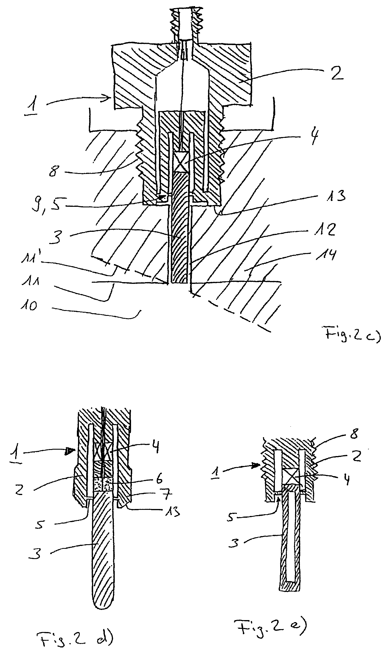
[0006]The idea underlying the invention is that the pressure sensor according to the invention includes a housing element embodied as a pin and protruding from the housing. The advantage of this arrangement is that only a small drilling to a pressure chamber need be provided to carry out a pressure measurement. The pin need only be so long that the front end thereof, in the assembled state, extends at least approximately to the wall of the pressure chamber. Particularly, the drilling provided for this purpose need not be perpendicular with respect to the wall of the pressure chamber. Another advantage of this arrangement is that the measuring cell is not immediately adjacent to the pressure chamber and thus need not inevitably be high-temperature resistant even if high temperatures domi...


PUM

PropertyMeasurementUnit
pressureaaaaaaaaaa
lengthaaaaaaaaaa
diameteraaaaaaaaaa

Abstract

The invention relates to a pressure sensor (1), comprising a housing (2), a housing element (3) which may be exposed to a pressure chamber (10), mounted on the housing (2) by means of a metallic membrane (5) and a measuring cell (4) which can indirectly measure a pressure acting on the housing element (3) and transmitted to the measuring cell (4) as a force resulting therefrom. According to the invention, said pressure sensor (1) comprises a housing element (3) embodied as a pin and projects out of the housing (2). The advantage of such an arrangement is only a small drilling to a pressure chamber (10) need be provided, in order to carry out a pressure measurement. The pin (3) need only be so long that the front end thereof, in the assembled state, approximately reaches the wall (11) of the pressure chamber (10).

Description

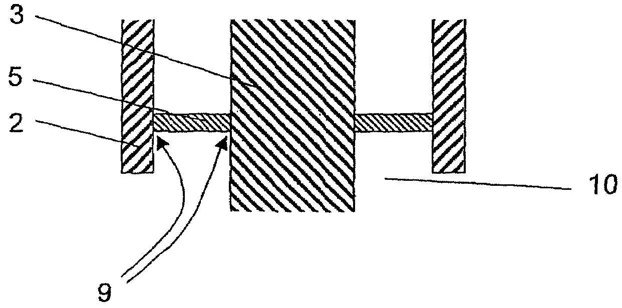
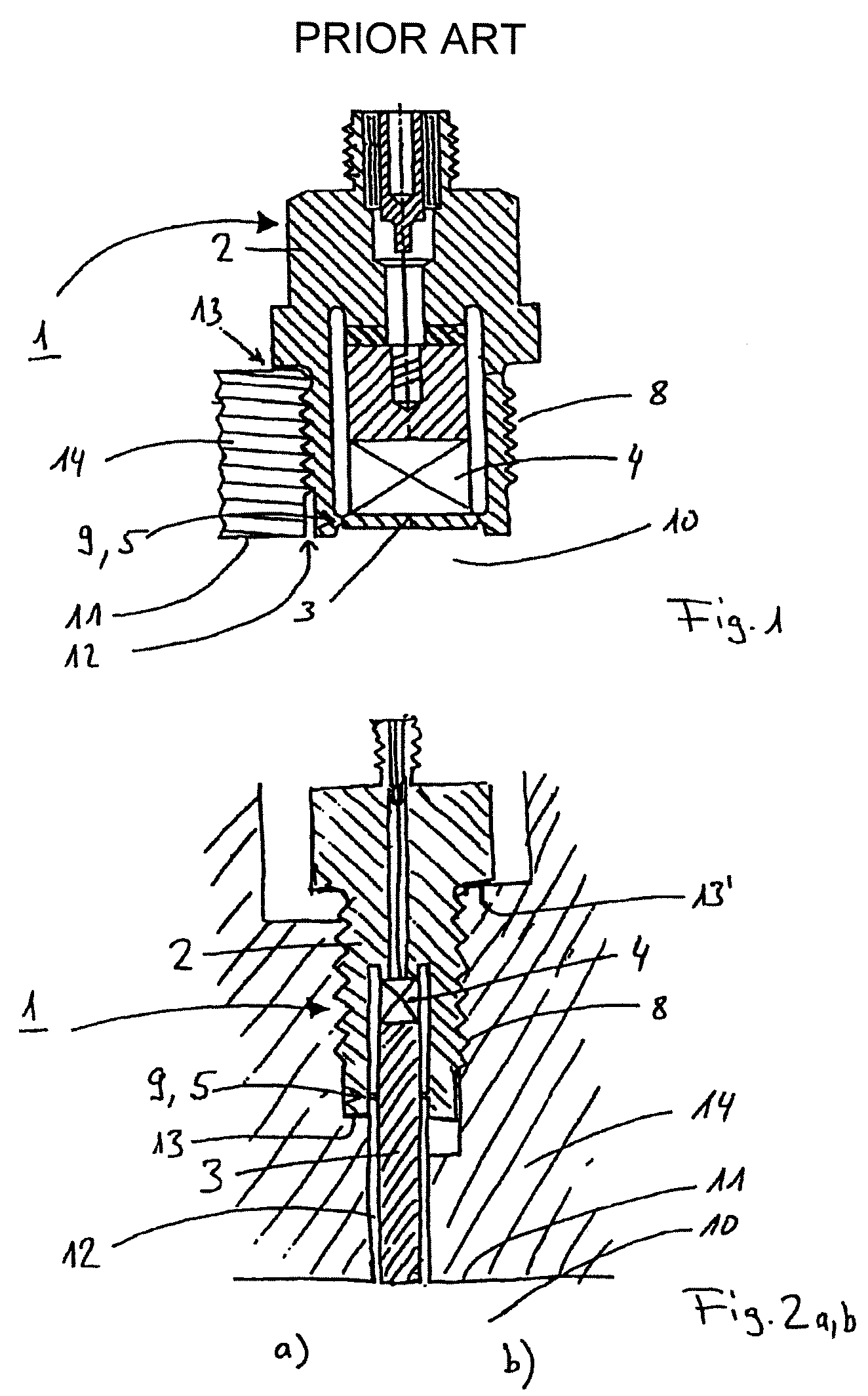
TECHNICAL FIELD[0001]The invention relates to a pressure sensor that has a housing which may be mounted to the work piece (14) of a pressure chamber (10).PRIOR ART[0002]FIG. 1 shows a schematic representation of a pressure sensor 1 according to the prior art in cross section. Typically, it has a housing 2 and a measuring cell 4 with a housing element installed adjacently thereto which is able to transmit a pressure from a pressure chamber 10 onto the measuring cell 4. The housing element 3 which is typically a thin plate or membrane is welded to the housing 2 at a welding site 9 which on the one hand functions as a seal for the interior of the pressure sensor 1 with respect to the pressure chamber 10 and on the other hand ensures the mobility of the housing element 3. By means of a thread 8 the pressure sensor 1 can be installed in a mounting opening 12 provided therefor in a wall 11 of a work piece 14 so that the outer surface of the housing element 3 extends approximately continuo...

Claims


Application Information

Patent Timeline
Patent Type & Authority Patents(United States)
IPC IPC(8): G01L9/00
CPCG01L9/0089G01L23/10G01L23/22B29C45/77
Inventor WOLFER, PETERHESS, REINHOLDMUELLER, MICHAELCAVALLONI, CLAUDIOKERN, CHRISTOPHSCHOTT, STEFFENSALTIKOV, PAVLOLUDWIG, THOMASKRUEGER, JUERGEN
Owner ROBERT BOSCH GMBH
Learn More