
PCI-E automatic allocation system

a technology of automatic allocation and allocation system, applied in the direction of electrical digital data processing, instruments, electrical apparatus, etc., can solve the problems of data loss or service interruption, inconvenient and complex aforesaid practice, etc., and achieve the effect of speeding up data transmission and slowing down data transmission

Inactive Publication Date: 2008-11-04
INVENTEC CORP
View PDF2 Cites 31 Cited by
  • Summary
  • Abstract
  • Description
  • Claims
  • Application Information

AI Technical Summary

Benefits of technology

[0011]Accordingly, to overcome the drawbacks of the aforementioned prior art, it is a primary objective of the present invention to provide a Peripheral Component Interconnection Express (PCI-E) automatic allocation system to enhance the use of PCI-E lanes and speed up data transmission.
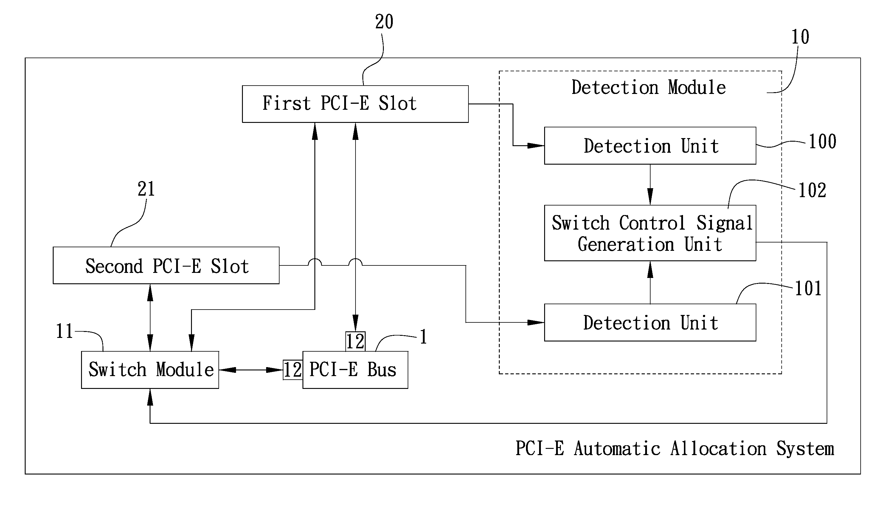
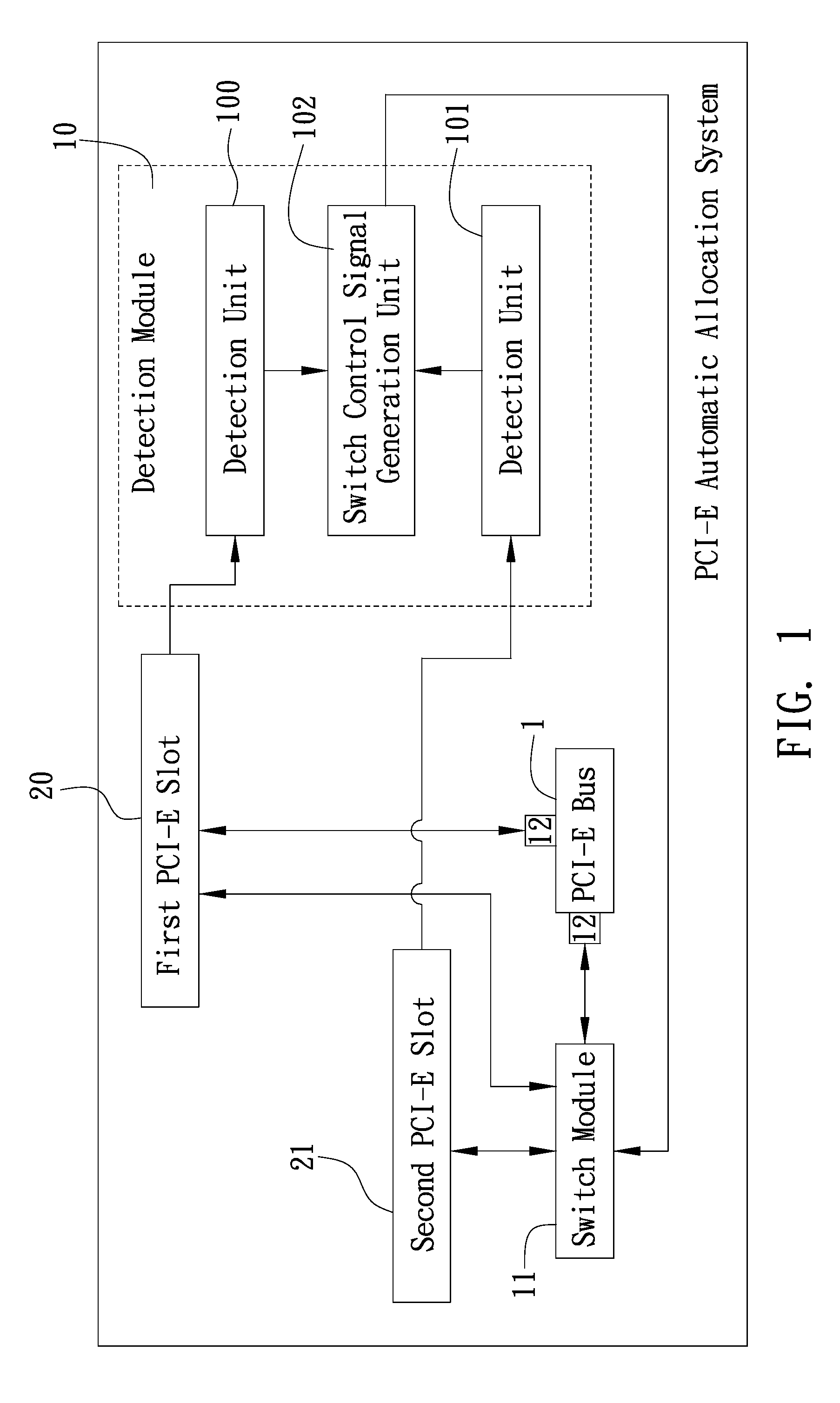
[0017]Compared with the prior art, the PCI-E automatic allocation system of the present invention uses a detection module to detect the states of the logic signals on the ground pins of a first and second PCI-E slots in a computer system, so as to determine whether the first and second PCI-E slots hold any expansion card; if the detection module detects an expansion card in the first PCI-E slot rather than the second PCI-E slot, then a switch control signal is generated to control the switch operation performed by a switch module, that is, transferring lane availability from the second PCI-E slot to the first PCI-E slot. Hence, according to the present invention, PCI-E lanes previously assigned to the second PCI-E slot with small lane width are reassigned to the first PCI-E slot with large lane width, so as to speed up data transmission between the expansion card inserted in the first PCI-E slot and the computer system, use PCI-E lanes efficiently, and overcome the drawbacks of the prior art, such as inefficient use of PCI-E lanes arising out of fixed connection between a PCI-E lane and a PCI-E slot, slow data transmission, and inflexible PCI-E bus design.

Problems solved by technology

However, upon the introduction of any new accompanying peripheral, the computer has to be restarted in order to finalize the installation of the peripheral, and in consequence it necessitates interrupting current operations.
The aforesaid practice is both intricate and inconvenient, and it could have a devastating consequence, such as data loss or service interruption, especially in the case of those devices with strict persistence and reliability requirements, for example, servers.
As devices evolved, new bandwidth hungry devices began starving other devices on the same shared bus.
As a result, networking speed is inevitably compromised.
More badly, with other computer accessories being upgraded, current PCI technology is becoming less fit to meet the computer system requirements, thus prompting the advent of a new technology which will substitute for the existing PCI technology and supply more bandwidth to a computer system.
However, in a situation where an expansion card is inserted in the PCI-E ×8 slot rather than the PCI-E ×4 slot, the aforesaid rule, that is, the PCI-E lanes being evenly allocated to the PCI-E ×4 slot and the PCI-E ×8 slot, makes the lanes associated with PCI-E ×4 slot idle, and in consequence part of the PCI-E lanes are not efficiently used; hence, resultant disadvantages are, namely slow data transmission, a waste of I / O bandwidth of the PCI-E bus, and inflexible PCI-E bus design.
Accordingly, an issue that currently confronts the industry and needs urgent solution involves developing a PCI-E automatic allocation technology to promote efficient use of PCI-E lanes and overcome the drawbacks of the prior art, such as inefficient use of PCI-E lanes arising out of inflexible allocation of PCI-E lanes, slow data transmission, and inflexible PCI-E bus design.

Method used


Image

  • PCI-E automatic allocation system
  • PCI-E automatic allocation system

Examples


Embodiment Construction

[0019]The following specific embodiments are provided to illustrate the present invention. Others skilled in the art can easily understand other advantages and features of the present invention in accordance with the contents disclosed in this specification. The present invention can also be performed or applied by other different embodiments. Various modifications and changes based on different viewpoints and applications yet still within the scope of the present invention can be made in the details of the specification.

[0020]Referring to FIG. 1, which is a block diagram of the structure of a PCI-E automatic allocation system according to the present invention. The PCI-E automatic allocation system of the present invention is applied in a computer system (not shown). The computer system comprises at least two PCI-E slots; the first and second PCI-E slots 20 and 21 are herein illustrated with a diagram, to simplify illustration and explanation. In addition, the computer system is on...


PUM


Abstract

A PCI-E automatic allocation system which essentially consists of a detection module and a switch module, wherein the detection module detects the states of the logic signals on the ground pins of a first PCI-E slot with large lane width and a second PCI-E slot with small lane width in a computer system, to determine whether the first and second PCI-E slots hold any inserted expansion card; if the detection module detects an inserted expansion card in the first PCI-E slot rather than the second PCI-E slot, a switch control signal output is generated, to control the switch operation performed by the switch module, that is, transferring lane availability from the second PCI-E slot to the first PCI-E slot, with a view to enhancing the use of PCI-E lanes, speeding up data transmission, and overcoming a known drawback of PCI-E buses, that is, inflexible design.

Description

BACKGROUND OF THE INVENTION[0001]1. Field of the Invention[0002]The present invention relates to a PCI-E automatic allocation system, and more particularly, to a system applied in a computer system to allocate lanes for PCI-E buses.[0003]2. Description of the Prior Art[0004]With constant advancement of electronic and computer technology, resultant computer functions are not only increasingly powerful but also subject to upgrades or supplements emerging in the presence of new accompanying peripherals. However, upon the introduction of any new accompanying peripheral, the computer has to be restarted in order to finalize the installation of the peripheral, and in consequence it necessitates interrupting current operations. The aforesaid practice is both intricate and inconvenient, and it could have a devastating consequence, such as data loss or service interruption, especially in the case of those devices with strict persistence and reliability requirements, for example, servers.[000...

Claims


Application Information

Patent Timeline
Patent Type & Authority Patents(United States)
IPC IPC(8): G06F13/40
CPCG06F13/4081G06F2213/0026
Inventor CHEN, KUN-FU
Owner INVENTEC CORP
Learn More