
Connector

a technology of connecting rods and connectors, applied in the direction of couplings/cases, coupling device connections, electrical devices, etc., can solve the problems of connectors not being able to connect properly with the mating connectors, the height of the sealant may be too high, and the connection between the connector and the mating connector may not be convenien

Active Publication Date: 2008-11-04
SUMITOMO WIRING SYST LTD
View PDF12 Cites 27 Cited by
  • Summary
  • Abstract
  • Description
  • Claims
  • Application Information

AI Technical Summary

Benefits of technology

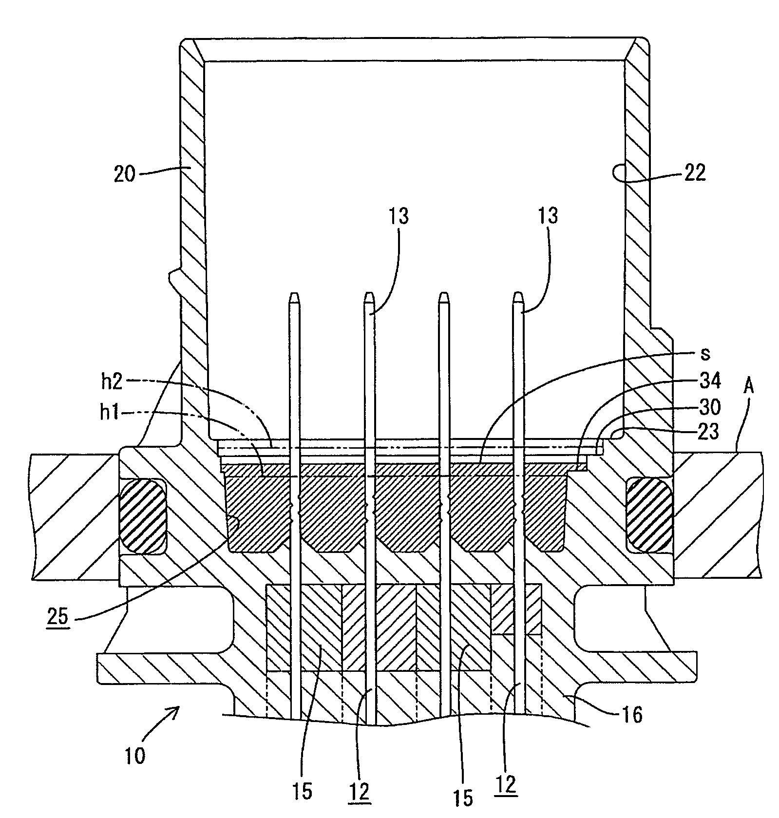
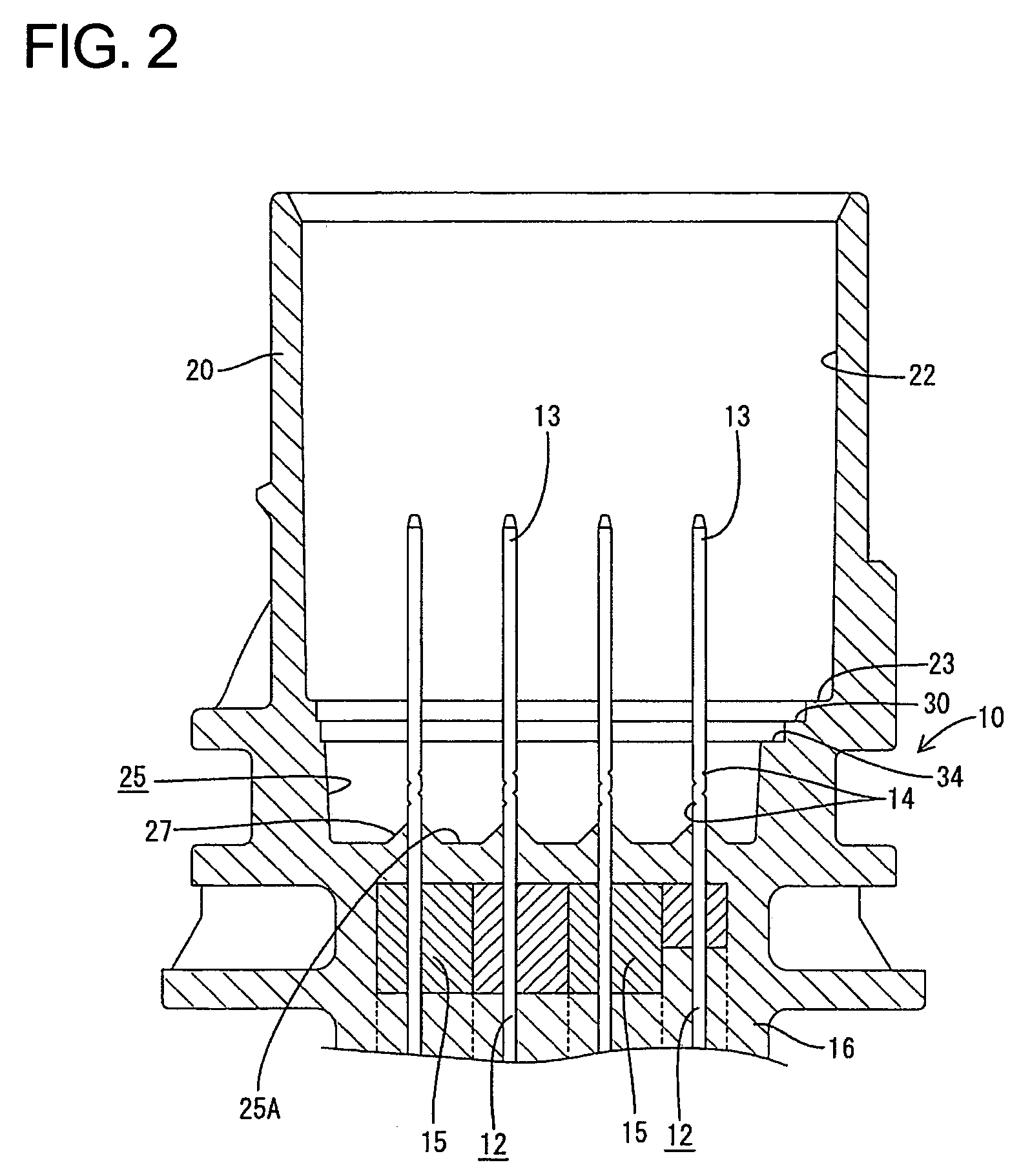
The invention is a connector with a main body made of synthetic resin and formed with a fitting recess for receiving a mating connector. Terminal fittings project from a bottom surface of the fitting recess. A sealant is filled substantially around base ends of the projecting terminal fittings. The bottom surface of the fitting recess is recessed in at least part of an area surrounding the projections of the terminal fittings to form a filling recess for the sealant. A diverging boundary surface is formed around at least part of the filling recess at a height corresponding to an upper limit of the sealant. A detecting surface is formed around the outer periphery of the filling recess. The filled amount of the sealant is proper when the sealant is at a height to cover only the detecting stepped surface. The visual confirmation area is formed by causing the shapes and positions of the filling recess and the diverging boundary surface to differ from each other. The terminal fittings preferably project up from the bottom surface of the fitting recess, and bite-in grooves are formed in the terminal fittings. Intermediate parts of the terminal fittings are embedded by insert molding in at least one primary molded piece by insert molding. The technical effects of the invention include precise detection of the sealant level through a wide visual confirmation area, and the use of bite-in grooves to improve sealant retention.

Problems solved by technology

The terminal fittings and the body may not be held in close contact due to poor affinity between the terminal fittings and the resin of the main body.
The height of the sealant may be too high if an excessive amount of the sealant is filled.
As a result, the connector may not connect properly with the mating connector.
However, sealing may be impaired if the filled amount is reduced to avoid this problem.
Therefore, it has been difficult to judge whether the filled sealant is at a suitable height.

Method used


Image

  • Connector
  • Connector
  • Connector

Examples


Embodiment Construction

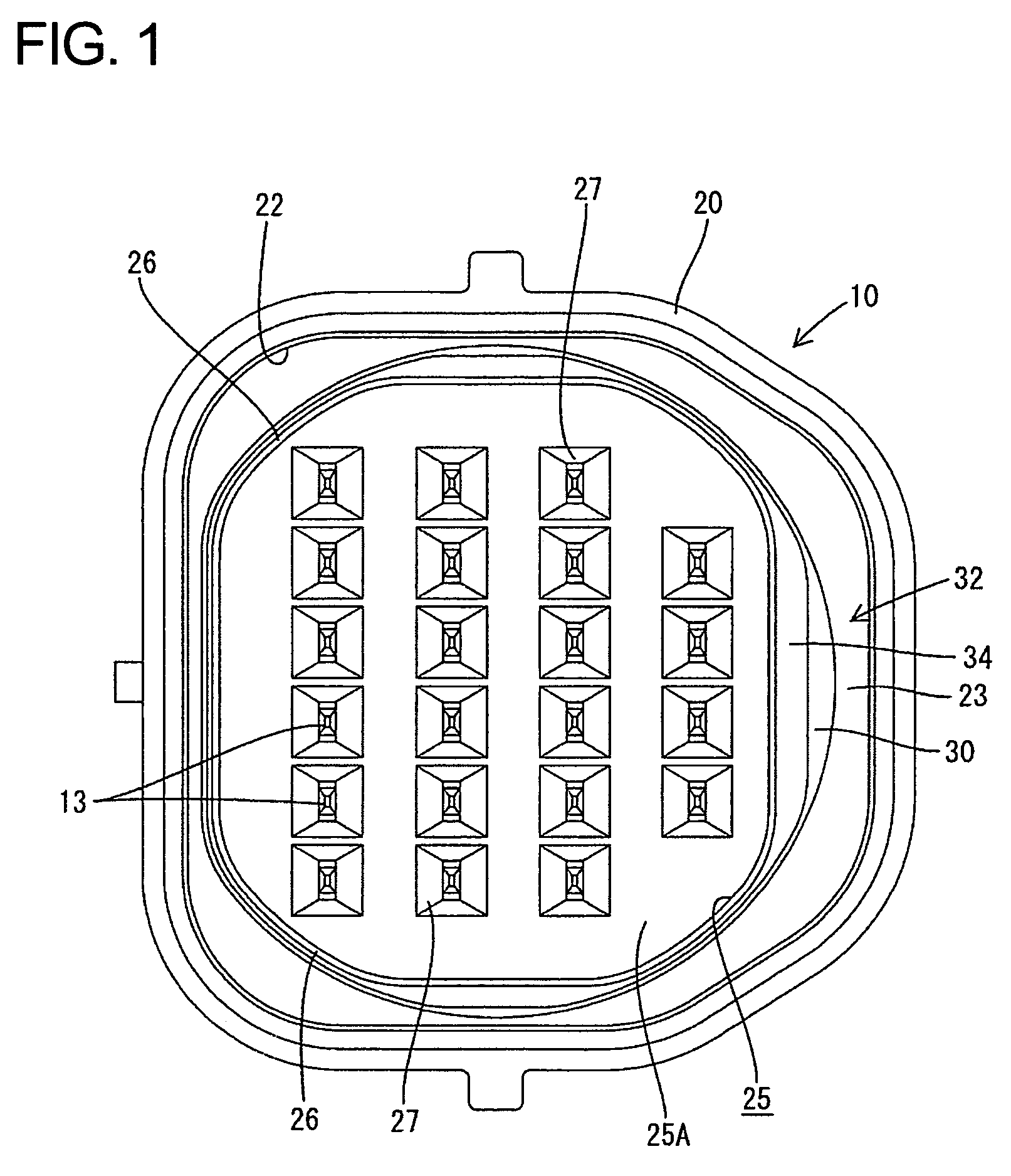
[0023]An intermediate connector for a transmission case is illustrated in FIGS. 1-6, as an example of the invention. This connector has connecting portions for mating connectors at two opposite ends and is mounted through a top plate A of the transmission case for electrical connection between devices inside and outside the transmission casing, as shown in FIG. 4. The construction of the connecting portion at the outer side where sealant is filled, i.e. so-called potting is applied, is described below.

[0024]A main body of the connector is identified by 10 in FIGS. 1 and 2 and is made e.g. of synthetic resin, such as Nylon 66, 33% glass filled. A receptacle 20 is formed at an upper end of the main body 10 and defines the connecting portion at the outer side. A fitting recess 22 is formed in the main body 10 for receiving an unillustrated mating female connector. Male terminals 12 are embedded in the main body 10 and are substantially aligned in the transverse and / or longitudinal dire...


PUM


Abstract

A filling recess (25) for a sealant “s” is formed in a bottom of a fitting recess (22) and a boundary stepped surface (30) is formed around the filling recess (25) to define an annular area between the filling recess (25) and the outer peripheral edge of the boundary stepped surface (30). A detecting stepped surface (34) is formed around the upper edge of the filling recess (25) and is slightly lower than the boundary stepped surface (30). A filled amount of the sealant “s” is proper if the detecting stepped surface (34) cannot be seen, but the boundary stepped surface (30) can be seen. The filled amount is too little if both stepped surfaces (34, 30) can be seen, and it is excessive if neither of the stepped surfaces (34, 30) can be seen.

Description

BACKGROUND OF THE INVENTION[0001]1. Field of the Invention[0002]The invention relates to a connector filled with sealant and to a molding method therefor.[0003]2. Description of the Related Art[0004]Japanese Unexamined Patent Publication No. H08-250193 discloses an intermediate connector with a body made of a synthetic resin and having opposite front and rear ends. A fitting recess is formed at the front of the body and is configured to receive a mating connector. Tab-shaped terminal fittings are embedded by insert molding while ends of the tab-shaped terminals project from the bottom surface of the fitting recess. The terminal fittings and the body may not be held in close contact due to poor affinity between the terminal fittings and the resin of the main body. Therefore, a sealant, such as epoxy resin, must be filled on the bottom of the fitting recess to ensure sealing.[0005]A filled amount of the sealant must be administered in the above-described connector. The height of the s...

Claims


Application Information

Patent Timeline
Patent Type & Authority Patents(United States)
IPC IPC(8): H01R13/52
CPCH01R13/521H01R13/5216H01R43/005Y10S439/936
Inventor NAGASHIMA, SHINYUMAEGAWA, AKIHITO
Owner SUMITOMO WIRING SYST LTD
Learn More