
Motorized bicycle derailleur assembly

a technology for derailleurs and bicycles, applied in cycle equipment, transportation and packaging, gearing, etc., can solve the problems of not always being as easily adjusted as desired by riders, prior motorized derailleurs that do not always operate reliably, and suffer from some deficiencies

Active Publication Date: 2008-10-28
SHIMANO INC
View PDF37 Cites 55 Cited by
  • Summary
  • Abstract
  • Description
  • Claims
  • Application Information

AI Technical Summary

Benefits of technology

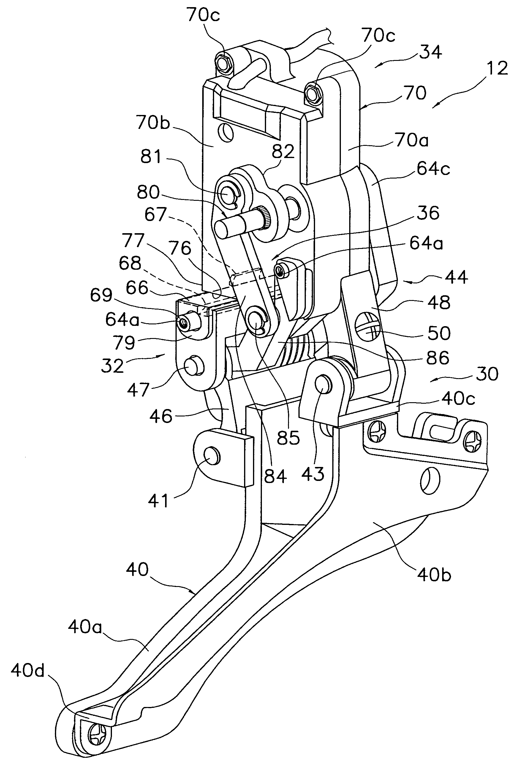
The present invention provides a motorized bicycle front derailleur assembly that is reliable, easy to adjust, includes a jamming protection connection, and is simple and inexpensive to manufacture and assemble. The assembly includes a motor unit, a front derailleur, and a motor linkage that is operatively coupled to the output shaft of the motor unit and the inner link of the front derailleur to move the chain guide from the inner shift position to the outer shift position upon rotation of the output shaft in the first rotational direction and to move the chain guide from the outer shift position to the inner shift position upon rotation of the output shaft in the second rotational direction.

Problems solved by technology

While these prior motorized derailleurs work relatively well, they do suffer from some deficiencies.
In particular, these prior motorized derailleurs do not always operate as reliably as desired by some riders.
Moreover, these prior motorized derailleurs are not always as easily adjusted as desired by some riders.
Furthermore, these prior derailleurs are not always as simple and inexpensive to manufacture and assemble as desired.
Finally, these prior motorized derailleurs often have a motor unit assembly, which requires numerous fasteners to couple the parts together, which can be relatively complicated.

Method used


Image

  • Motorized bicycle derailleur assembly
  • Motorized bicycle derailleur assembly
  • Motorized bicycle derailleur assembly

Examples


first embodiment

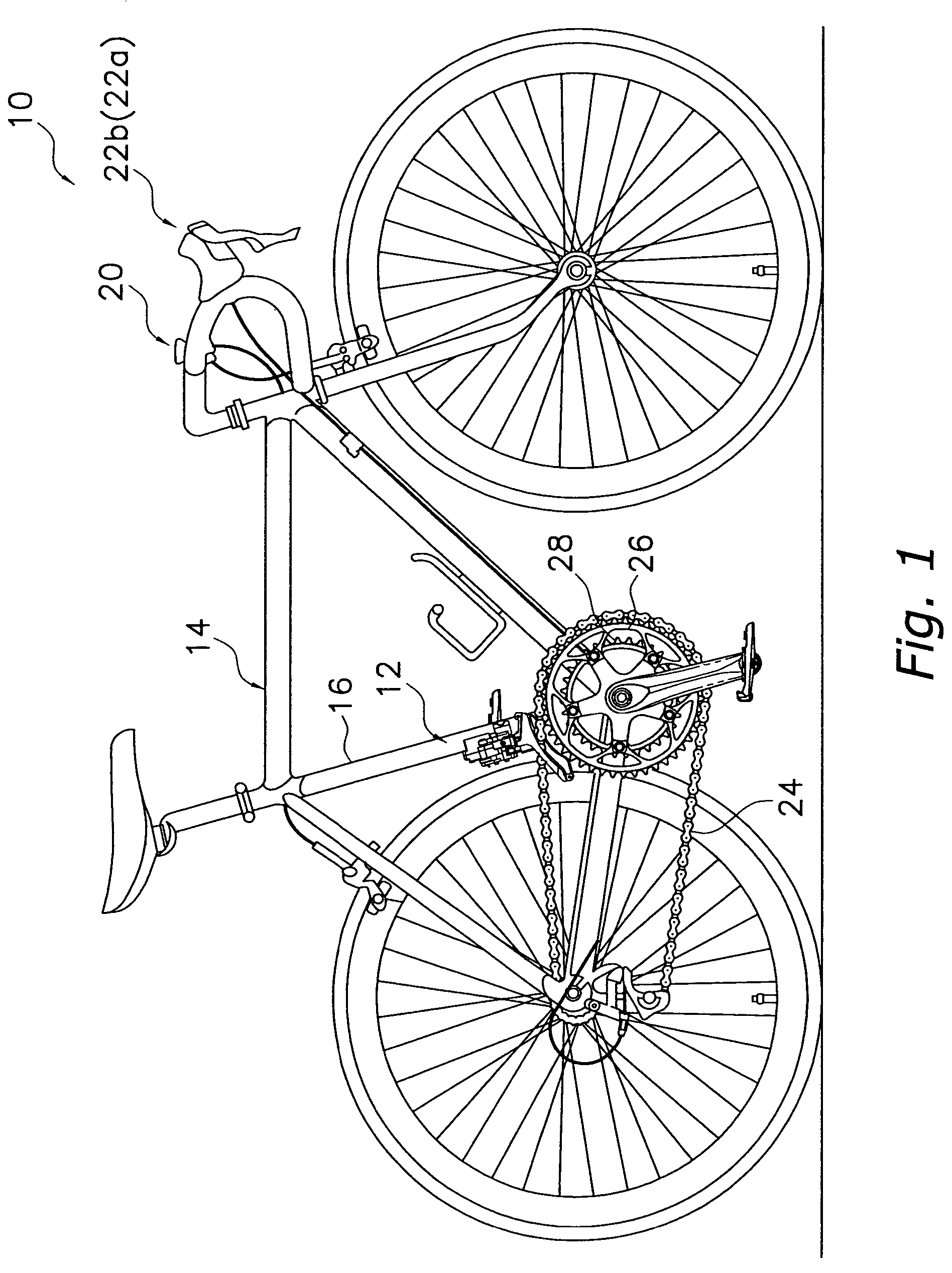
[0069]Referring initially to FIGS. 1-4, a bicycle 10 is illustrated that is equipped with a motorized bicycle front derailleur assembly 12 in accordance with the present invention. The bicycle 10 includes a bicycle frame 14 having a seat tube 16 with the motorized front derailleur assembly 12 mounted to the seat tube 16 by a bracket 18 and a plurality of fasteners or bolts 19, as best seen in FIGS. 2-4. The front derailleur assembly 12 is actuated / operated in a conventional manner by an electronic shifting unit 20 coupled to a front electrical shift control device 22a via an electric shift cable to move a chain 24 between at least two front sprockets or chain wheels 26 and 28.

[0070]The sprockets 26 and 28 are part of a bicycle drive train that includes a rear electrical shift control device 22b as well as various other conventional parts such as pedals, a crank set, one or more rear sprockets, a motorized rear derailleur, a freewheel and the chain 24. The electrical shift control de...

second embodiment

[0097]The internal motor structure 72 of front derailleur motor unit 34 is mounted within the housing 70. The internal motor structure 72 preferably includes a reversible electric motor that is powered by a battery source or a generator, a drive train including a plurality of gears operatively coupled between the electric motor and the output shaft 80, and a position control device that includes various electronic components (e.g. printed circuit board, photo interrupter, top-low brush sensor, etc.) for controlling operation of the electric motor. The internal motor structure 72 is electrically coupled to the shifting unit 20 by an electrical cord and to a power source (battery source or generator) by another electrical cord. Internal motor structures such as the internal motor structure 72 are well known. Thus, the internal motor structure 72 will not be discussed or illustrated in detail. Rather, the internal motor structure 72 can be understood from the second embodiment U.S. pat...


PUM


Abstract

A motorized bicycle front derailleur assembly is provided that includes a motor unit, a front derailleur and a motor linkage. The motor unit is configured to rotate an output shaft in first and second opposite rotational directions. The front derailleur includes a fixing body configured to be mounted to a bicycle frame, inner and outer links pivotally coupled to the fixing body at first and second pivot points, and a chain guide pivotally coupled to the inner and outer links to move between an inner shift position and an outer shift position. The first pivot point is located laterally closer to a center plane of the bicycle frame than the second pivot point. The motor linkage is operatively coupled to the output shaft of the motor unit and the inner link to move the chain guide between the inner and outer shift positions upon rotation of the output shaft.

Description

BACKGROUND OF THE INVENTION[0001]1. Field of the Invention[0002]This invention generally relates to a motorized bicycle derailleur assembly. More specifically, the present invention relates to a motorized bicycle front derailleur assembly with a drive link coupled to an inner link to move the chain guide laterally outwardly when a pulling force is applied to the inner link.[0003]2. Background Information[0004]Bicycling is becoming an increasingly more popular form of recreation as well as a means of transportation. Moreover, bicycling has become a very popular competitive sport for both amateurs and professionals. Whether the bicycle is used for recreation, transportation or competition, the bicycle industry is constantly improving the various components of the bicycle. In fact, bicycles have recently been equipped with electrical components to make riding easier and more enjoyable for the rider. Some bicycles are equipped with automatic shifting units that are automatically adjuste...

Claims


Application Information

Patent Timeline
Patent Type & Authority Patents(United States)
IPC IPC(8): F16H9/00F16H59/00F16H61/00F16H63/00B62M9/132
CPCB62M9/132B62M25/08Y10T74/20438
Inventor ICHIDA, TADASHIFUJII, KAZUHIRO
Owner SHIMANO INC
Learn More