
Base for a cartridge casing body for an ammunition article, a cartridge casing body and an ammunition article having such base, wherein the base is made from plastic, ceramic, or a composite material

a technology for ammunition articles and cartridge casings, which is applied in the field of ammunition articles with plastic components, can solve the problems of excessive chamber pressure, plastic cartridge casings, and inability to provide satisfactory ammunition that could be produced in commercial quantities with sufficient safety, ballistic and handling characteristics, and achieves the effect of reducing manpower and equipmen

Inactive Publication Date: 2008-10-28
DEV CAPITAL MANAGEMENT
View PDF4 Cites 201 Cited by
  • Summary
  • Abstract
  • Description
  • Claims
  • Application Information

AI Technical Summary

Problems solved by technology

Plastic cartridge casings have been known for many years but have failed to provide satisfactory ammunition that could be produced in commercial quantities with sufficient safety, ballistic, and handling characteristics.
The problems evidenced by all of the known methods of producing plastic or substantially plastic ammunition include the possibility of the projectile being pushed into the cartridge casing, the bullet pull being too light such that the bullet can fall out, the bullet pull being insufficient to create enough chamber pressure, the bullet pull being too great causing excessive chamber pressure, the bullet pull not being uniform from round to round, portions of the cartridge casing breaking off upon firing of the projectile causing damage or danger when subsequent rounds are fired or when the casing portions themselves become projectiles, and expense due to manufacturing techniques or multiple material constructions.
In the manufacture of blanks using plastic cartridge cases, similar problems to those present with prior art cartridge cases for conventional ammunition exist, as well as problems associated with portions of the cartridge cases breaking off and becoming dangerous, high velocity plastic projectiles.
However, the technique of forming a cartridge casing and then snapping a bullet into the casing is time consuming in that it involves multiple steps, is manpower and equipment intensive in that different equipment is necessary to perform various tasks in the manufacturing process, and still risks a less than perfect fit between bullet and casing in that the casings are not custom fit to each bullet.

Method used


Image

  • Base for a cartridge casing body for an ammunition article, a cartridge casing body and an ammunition article having such base, wherein the base is made from plastic, ceramic, or a composite material
  • Base for a cartridge casing body for an ammunition article, a cartridge casing body and an ammunition article having such base, wherein the base is made from plastic, ceramic, or a composite material
  • Base for a cartridge casing body for an ammunition article, a cartridge casing body and an ammunition article having such base, wherein the base is made from plastic, ceramic, or a composite material

Examples


Embodiment Construction

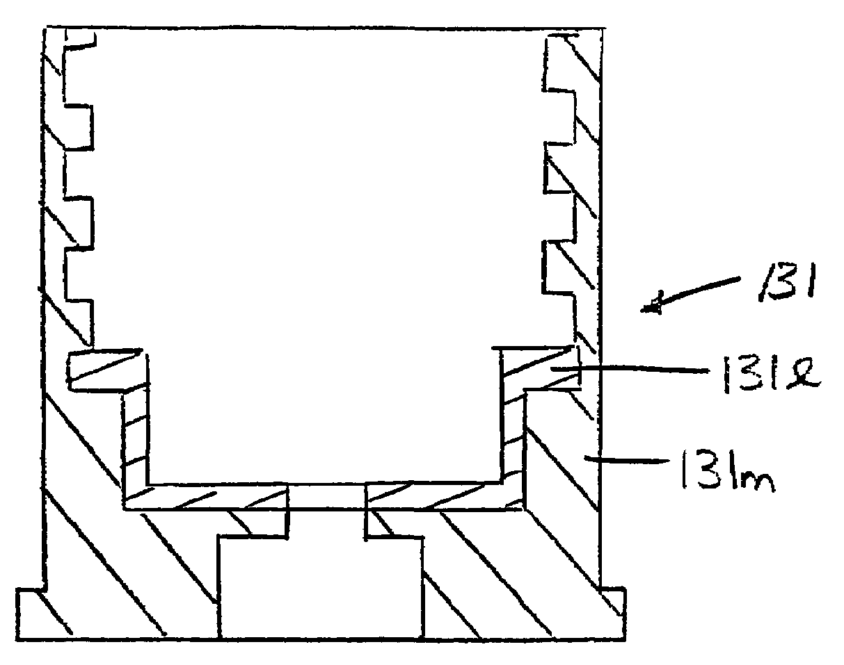
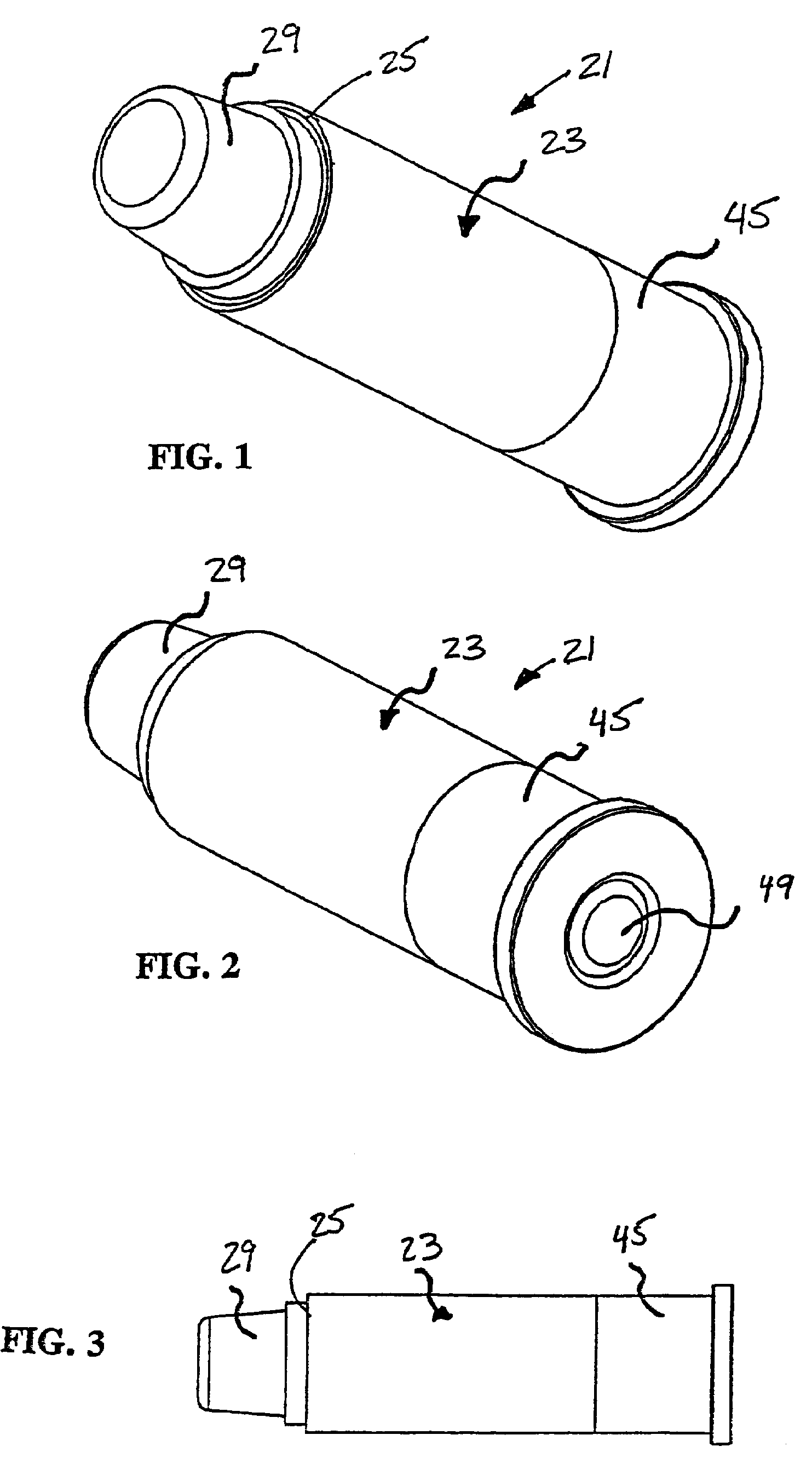
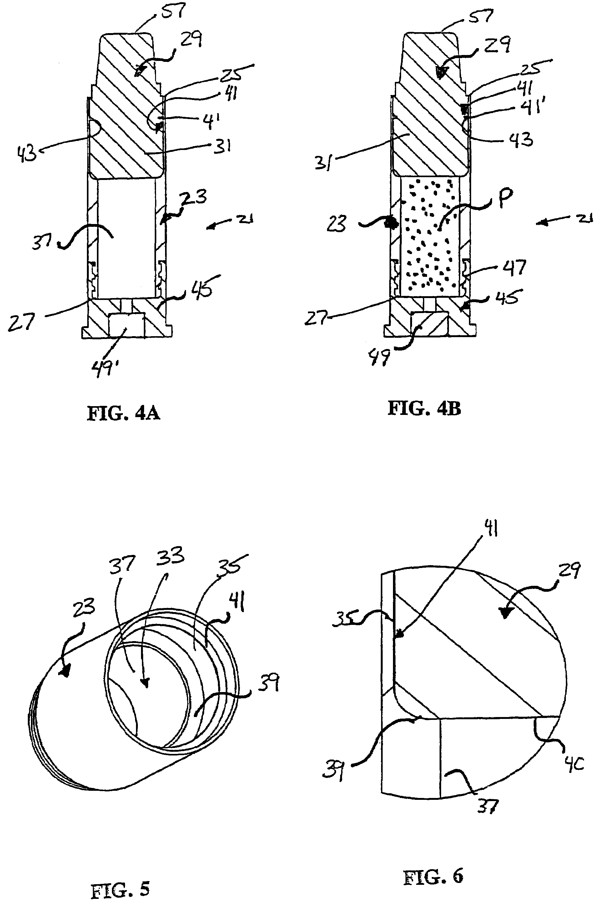
[0045]An ammunition article 21 according to an embodiment of the present invention is shown in FIGS. 1-3. As seen in cross-section in FIGS. 4A and 4B, the ammunition article 21 includes a molded plastic cartridge casing body 23 having a first end 25 and a second end 27. A projectile 29 is attached to the first end 25 of the cartridge casing body 23. The cartridge casing body 23 is a molded plastic part, and is formed by plastic being molded around at least a portion 31 of the projectile 29. As discussed with reference to FIG. 29, if desired or necessary, the cartridge casing body may be formed by plastic being molded to conform only with a bottom of a projectile, with a plastic protrusion extending into a cavity in the bottom of the projectile. The projectile 29 is preferably any one of the wide variety of well-known projectiles but may, if desired or necessary, include one or more features useful in connection with the present invention.

[0046]As seen in FIG. 5 (showing the cartridg...


PUM


Abstract

A base for a cartridge casing body for an ammunition article, the base having a ignition device; an attachment device at one end thereof, the attachment device being adapted to attach the base to a cartridge casing body; wherein the base is made from plastic, ceramic, or a composite material.

Description

CROSS-REFERENCE TO RELATED APPLICATIONS[0001]This application is a continuation-in-part of U.S. patent application Ser. No. 10 / 912,162, filed on Aug. 6, 2004, which is a divisional of U.S. patent application Ser. No. 09 / 832,020, filed on Apr. 11, 2001 and now U.S. Pat. No. 6,845,716, which is a divisional of U.S. patent application Ser. No. 09 / 265,946, filed on Mar. 11, 1999 and now U.S. Pat. No. 6,752,084, and which claims the benefit of U.S. Provisional Application No. 60 / 116,232, filed Jan. 15, 1999. The subject matter of U.S. patent application Ser. No. 10 / 912,162, U.S. patent application Ser. No. 09 / 832,020, U.S. patent application Ser. No. 09 / 265,946, and U.S. Provisional Application No. 60 / 116,232 is incorporated herein by reference.FIELD OF THE INVENTION[0002]The present invention relates to ammunition articles and methods of making ammunition articles and, more particularly, to ammunition articles with plastic components such as cartridge casing bodies and bases, and method...

Claims


Application Information

Patent Timeline
Patent Type & Authority Patents(United States)
IPC IPC(8): F42B5/30F42B5/307F42B10/00
CPCF42B5/30F42B5/307F42B5/067F42B33/001
Inventor HUSSEINI, NABILBYRON, DAVID E.
Owner DEV CAPITAL MANAGEMENT
Learn More