
Headband apparatus for head-worn optical instruments

a technology for optical instruments and headbands, applied in the direction of othalmoscopes, garments, diagnostics, etc., can solve the problems of substantial impairment of the operating comfort of left-handers, substantial outlay on development and production, and the known headband apparatus does not provide any additional devices for fastening supplementary apparatuses or units

Active Publication Date: 2008-10-28
HEINE OPTOTECHN
View PDF12 Cites 45 Cited by
  • Summary
  • Abstract
  • Description
  • Claims
  • Application Information

AI Technical Summary

Benefits of technology

"The invention is a headband apparatus for a head-worn optical instrument that can be used with a variety of additional elements such as a latching device, controller, and camera. The headband has fastening elements that allow for easy attachment of these additional elements. The latching device can be mounted on either side of the head and is releasably fastened, allowing for easy adjustment and replacement. The fastening elements are connected to a connecting lug, which is decoupled from the headband, and a locking element is used to secure the latching device in place. The technical effects of this invention are its versatility and ease of use with various additional elements."

Problems solved by technology

If the latching device is arranged for right-handers, as is normally the case, this constitutes a substantial impairment of the operating comfort for a left-hander.
For this reason, the manufacturer finds it necessary to make separate headband apparatuses available both for left-handers and right-handers, thus giving rise to substantial outlay on development and production.
Moreover, the known headband apparatus does not provide any additional devices for fastening supplementary apparatuses or units.

Method used


Image

  • Headband apparatus for head-worn optical instruments
  • Headband apparatus for head-worn optical instruments
  • Headband apparatus for head-worn optical instruments

Examples


Embodiment Construction

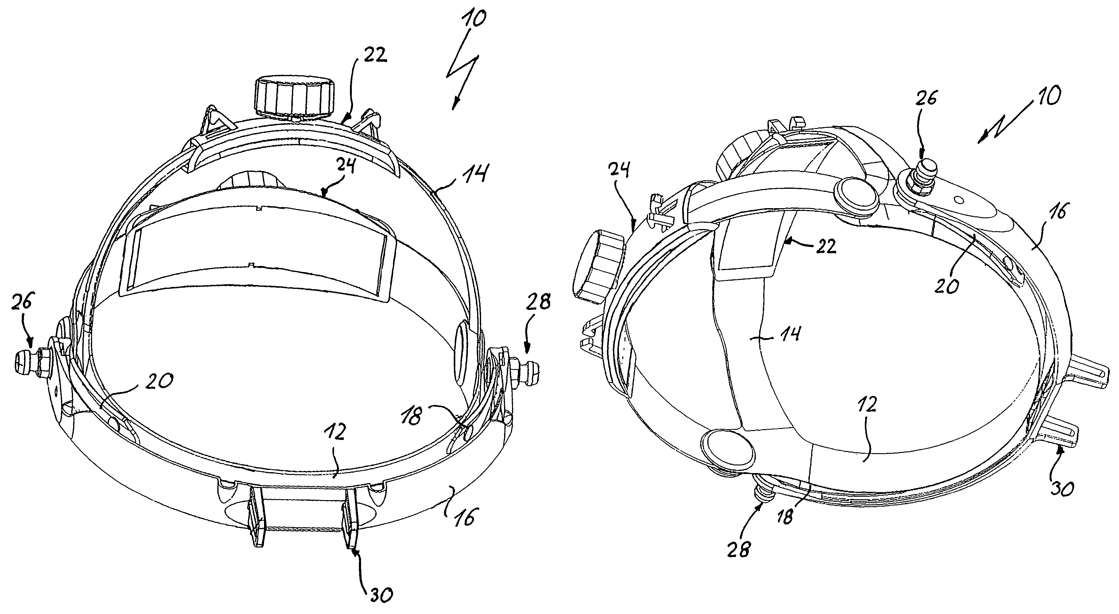
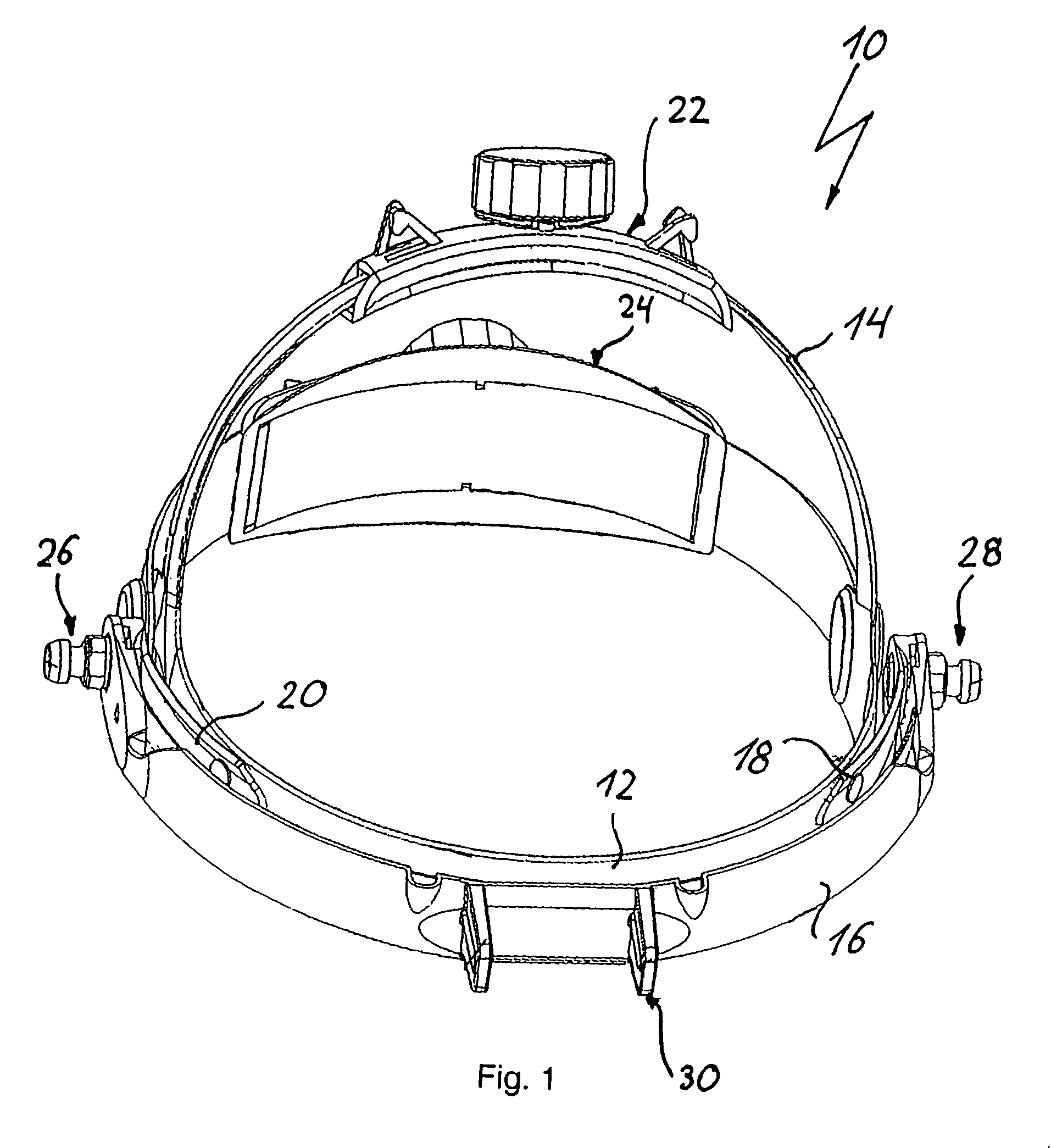
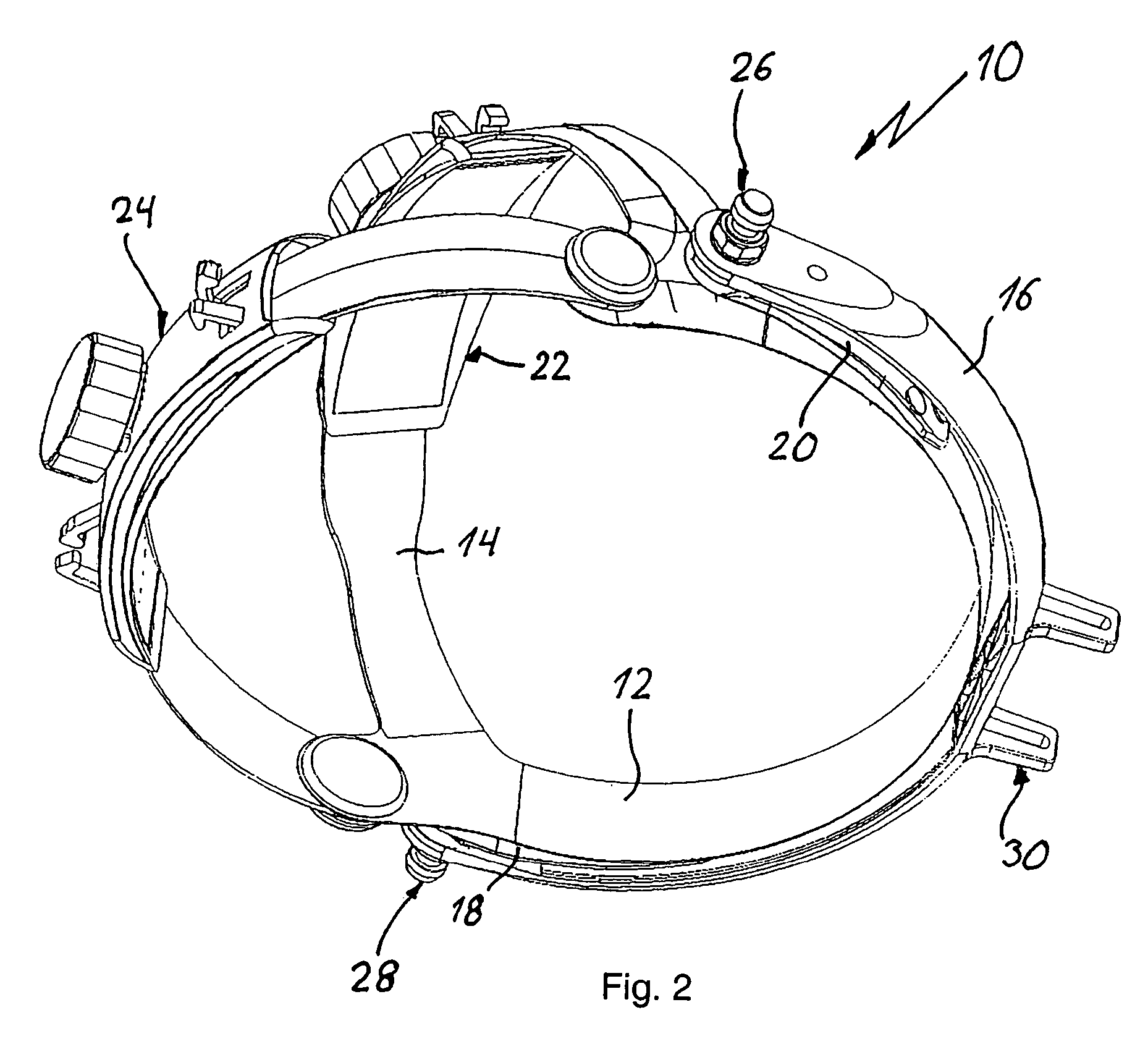
[0024]The headband apparatus 10 shown in FIGS. 1 and 2 comprises a headband 12 that can be adjusted by an adjusting device 24 and of which a crown band 14, which can be adjusted by an adjusting device 22, extends upward. In the front region, surrounding the user's forehead, of the headband 12, connecting lugs 18, 20 are fastened on both sides at one end and extend to the respective middle region of the side. At the free end of the connecting lugs 18, 20, one end of a bow 16 is swivelably supported in each case by fastening elements 26, 28. In the position shown in FIGS. 1 and 2, the bow 16 is located in a substantially horizontal position in which it surrounds the front region of the headband 12. A fastening device 30 for fastening an ophthalmoscope is provided at the middle region of the bow 16.

[0025]The bow 16 is formed by a molded plastic part, the electric supply cables being integrated in the bow.

[0026]FIGS. 3 and 4 show perspective illustrations of the headband apparatus 10 in...


PUM


Abstract

A headband apparatus for head-worn optical instruments includes a headband (12) and a bow (16) on which the optical instrument is fitted, and which is fitted with both its ends (100) to the middle region of the headband (12) such that it can swivel about a swivel axis (S) between a working position and a rest position. Fastening elements (26, 28) for releasably fastening additional elements (38) are fitted on the headband (12).

Description

BACKGROUND OF THE INVENTION[0001]1. Field of the Invention[0002]The invention relates to a headband apparatus for an optical instrument comprising a headband and a bow on which said optical instrument is mounted, said bow being mounted with both ends thereof at a middle region of said headband for swiveling about a swivel axis between a working position and a rest position.[0003]2. Description of the Background Art[0004]Such a headband apparatus known from U.S. Pat. No. 4,681,413 comprises an elastic headband surrounding the forehead and back of the head, and a crown band permanently connected thereto. The headband and the crown band can be adapted to the size and shape of the wearer's head with the aid of adjusting apparatuses. A bow is swivelably supported with its two ends in the middle side region of the headband. A binocular ophthalmoscope is fastened on the front side of the bow. The bow can be swiveled upward from a substantially horizontal working position, in which the opht...

Claims


Application Information

Patent Timeline
Patent Type & Authority Patents(United States)
IPC IPC(8): A42B1/22A61B3/13A61B19/00
CPCA61B19/26A61B3/132A61B2019/262A61B90/50A61B2090/502
Inventor HEINE, HELMUTHEINE, OLIVERSCHNEIDER, ANTON
Owner HEINE OPTOTECHN
Learn More