
Device for muscle stimulation

a technology for muscle stimulation and muscle fibers, applied in electrotherapy, physical therapy, artificial respiration, etc., can solve the problems of generating muscle fibers, weak and slow, fiber transformation, etc., and achieve the effect of preventing muscle destruction from excessive stress and less fatigu

Inactive Publication Date: 2008-10-07
FIDES FINANZ INVEST
View PDF8 Cites 0 Cited by
  • Summary
  • Abstract
  • Description
  • Claims
  • Application Information

AI Technical Summary

Benefits of technology

[0007]It is therefore an object of the invention to provide a muscle stimulator which makes it possible to preserve type-IIa muscle fibers and, more particularly, to provide an effective heart muscle assist system which operates when needed. The muscle stimulator should also be capable of inducing, through suitable electrical stimulation, the formation of new blood vessels and capillaries for optimally supplying the muscle tissue with blood (neo-vascularization).
[0013]To prevent the stimulated muscles from being overstimulated and the stimulated muscle fibers from being transformed into a weak, slow and hence ineffective type-I muscle tissue, the stimulation pulses transmitted within a definable time interval must be counted and evaluated. This task is performed by the counting unit in cooperation with the storage unit and a monitoring unit. The mean stimulation frequency is a measure for the frequency with which the muscles are stimulated during a certain time interval. To prevent muscle damage, the mean stimulation frequency must not continuously exceed an individually determined limit value.
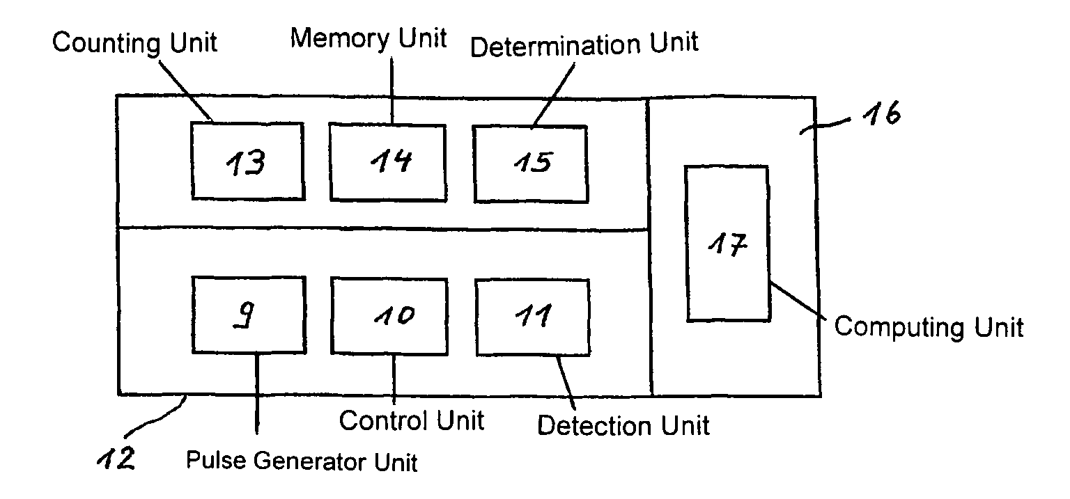
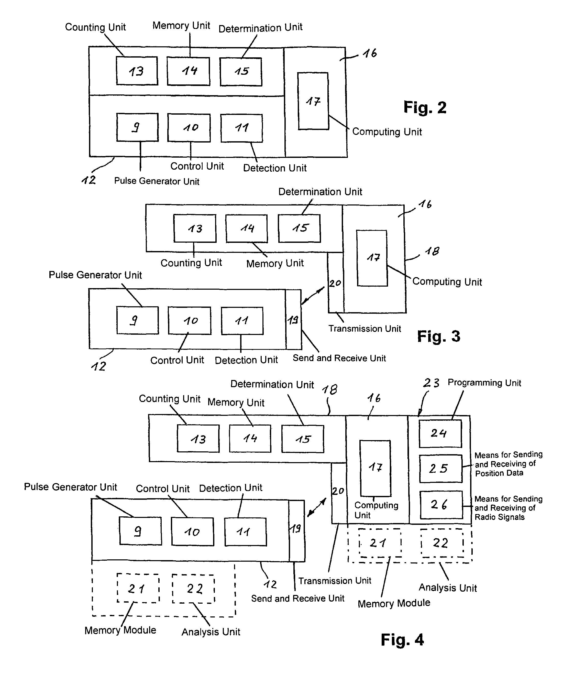
[0014]Each transmitted stimulation pulse is counted and computed over an extended observation time to yield a mean stimulation frequency. A longer observation time according to the invention has a duration of at least 30 minutes, in particular one hour or several hours. Advantageously, observation times are 12 or 24 hours. The mean stimulation frequency must be determined individually for each patient and must not exceed a maximum value of the 0.2 to 2 pulses per second (Hz), in particular 0.7 to 1 Hz, so as to prevent overexertion of the muscle and a medium-term muscle destruction. The mean stimulation frequency should therefore be evaluated so as to arrive at the desired muscle transformation and preservation effect, and to control the transmission of stimulation pulses depending on the outcome of the evaluation. For this purpose, a continuously operating evaluation unit for observing the limit values for the mean stimulation frequency is provided, wherein the limit values can be individually set in a range of 0.2 stimulation pulses per second to 2 stimulation pulses per second. Pulse conservation means, also referred to as pulse saving means, are provided for adapting and, more particularly, reducing the mean stimulation frequency as a function of the measured mean stimulation frequency and the defined desired values of the evaluation unit. The pulse conservation means include a computing unit for computing a modified stimulation pattern according to an equation which depends on the mean stimulation frequency. In addition, a memory module for storing the temporal course of the number of supplied stimulation pulses can be provided, as well as means for program-controlled transmission of the mean stimulation frequency from the determination unit to the computing unit. Moreover, an analysis unit can be provided for determining when and how often certain limit values of the heart rate and / or of the mean stimulation frequency are exceeded or underrun.
[0015]The counting unit and the memory unit can be housed in the aforedescribed housing. The determination unit and / or the pulse conservation means can also be integrated in the housing. Optionally, the memory module and / or the analysis unit can also be integrated in the housing that houses the control unit. The housing can be implanted in the body of the wearer of the device of the invention. An energy storage device which can preferably be recharged transcutaneously can also be associated with the housing. This increases the operating time of the implanted part of the device.
[0017]It is another object of the invention to provide a combination of specially developed electronic devices for muscular heart assist systems, in particular for muscular blood pumps, capable of generating and maintaining type-IIa muscle fibers. The invention also relates to a myo-stimulator which can be programmed to preoperatively generate through percutaneous stimulation type-IIa muscle fibers showing less fatigue. This device can include an implantable myo-stimulator and a monitoring unit which effectively contracts the muscle with type-IIa muscle fibers, prevents conversion to type-I muscle fibers, and also prevents destruction of muscle from excessive stress. The monitoring unit associated with this implantable myo-stimulator can be used as a programming unit as well as a measurement and display device. The monitoring unit can transmit information either wireless or by a wired connection from the bio-stimulator to the patient or to the attending physician. Additional functions can be incorporated in this device, such as transmitting the ECG of the patient and / or a patient location system for emergencies. This device can also implement to a limited extent the aforedescribed functions in myo-stimulators of other manufacturers.

Problems solved by technology

Experiments on large animals have shown that a continuous and frequent application of stimulation burst causes a fiber transformation of the stimulated muscle tissue, with the generated muscle fibers being substantially free of fatigue, but weak and slow.
Stimulation above this upper limit causes the type-IIa muscle fibers to transformation into type-I muscle fibers, accompanied by a loss in muscle strength and quickness.
Muscular-driven heart assist systems then lose their effectiveness, so that the diseased heart can no longer be effectively relieved.
This can cause the supported muscle to completely degenerate.

Method used


Image

  • Device for muscle stimulation
  • Device for muscle stimulation
  • Device for muscle stimulation

Examples


Embodiment Construction

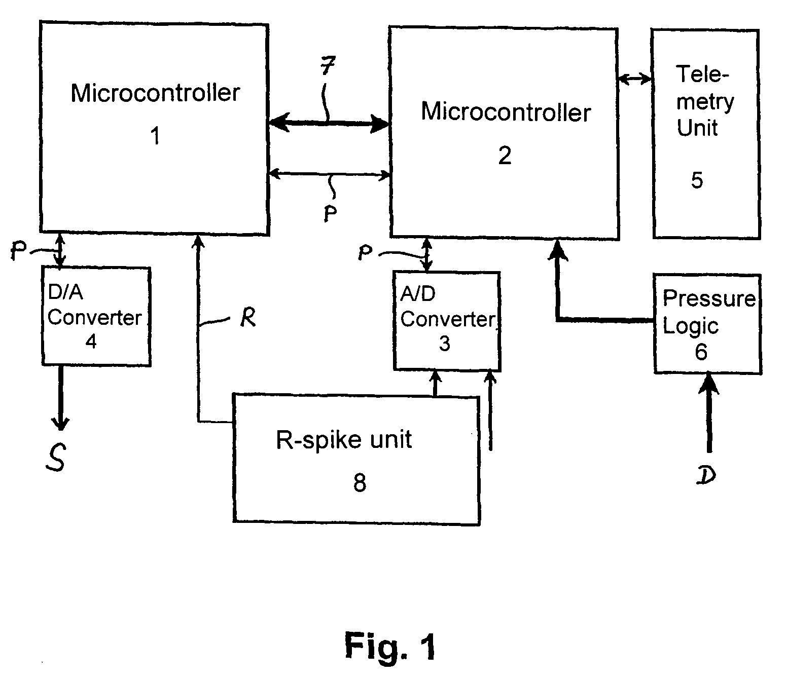
[0023]FIG. 1 depicts an embodiment with two microcontrollers 1, 2 as programmable components. The microcontrollers have a large number of programmable ports, a high processing speed with moderate power consumption, and a flash memory with in-system programmability (ISP). Additional components of the muscle pacemaker are a 12 bit analog-to-digital converter (A / D converter) 3, a 12 bit digital-to-analog converter (D / A converter) 4, several operational amplifiers, and a telemetry unit 5. Long-life batteries, preferably lithium ion batteries, supply power.

[0024]The digital portion of the muscle pacemaker is essentially divided into two logically separate regions, which are each operated with a dedicated microcontroller 1, 2 as programmable components. The first region, controlled by the microcontrollers 1, is used to generate, amplify and distribute the stimulation pulses S (max. 40 mA) to four muscle electrodes and two cardiac electrodes. The second region, controlled by the microcontr...


PUM


Abstract

The invention relates to a device for muscle stimulation, said device comprising a pulse generator unit (9) for producing and sending an electrical stimulation pulse; a control unit (10) for controlling the pulse generator unit (9) in order to adjust the amplitude and the frequency of the stimulation pulses and to cause the transmission of stimulation pulses to a muscle to be stimulated; a detection unit (11) for detecting the instantaneous, spontaneous or stimulated cardiac rhythm of the carrier of the device; a housing (12) receiving the pulse generator unit (9), the control unit (10), and the detection unit (11); a counting unit (13) and a memory unit (14) for counting and storing the number of stimulation pulses emitted within a definable time interval; and a determination unit (15) for determining the arithmetic average of the stimulation frequency within the definable time interval.

Description

BACKGROUND OF THE INVENTION[0001]The invention relates to a device for muscle stimulation.[0002]Muscle-driven heart assist systems (for example cardio myoplasty, aorta myoplasty, skeletal muscle ventricle, bio-mechanical hearts) are nowadays already employed in clinical settings, for example experimentally as assist or replacement therapy of heart transplantation and treatment of a terminal heart insufficiency. These muscle assist systems can operate both in parallel and in series with the diseased heart. The systems are intended to relieve (reduce the cardiac wall tension, relieve pressure, relieve volume, relieve post-stress) and also to assist the circulation, i.e., increase the average pressure of the arterial blood pressure and / or to increase the pump volume. Independent of the configuration of the heart assist system, a muscle pacemaker is required for deliberate stimulation of a muscle contraction, which transmits to the muscle to be assisted an electrical stimulation pattern...

Claims


Application Information

Patent Timeline
Patent Type & Authority Patents(United States)
IPC IPC(8): A61N1/36
CPCA61N1/36042
Inventor KLAPPROTH, PETERULBRICH, ECKART
Owner FIDES FINANZ INVEST
Learn More