
Methods and apparatus for implementing a wideband digital beamforming network

a beamforming network and wideband technology, applied in the direction of electrical equipment, antennas, etc., can solve the problems of increasing the complexity of control, increasing the number of interconnections, and impracticality of analog-based beamforming devices, etc., and achieves the effect of convenient operation

Active Publication Date: 2008-07-01
RAYTHEON CO
View PDF4 Cites 52 Cited by
  • Summary
  • Abstract
  • Description
  • Claims
  • Application Information

AI Technical Summary

Benefits of technology

The present invention provides a time delay circuit for a multi-element antenna that can apply different time delays to signals associated with different antenna elements. The time delay circuit includes a memory that stores beamforming control information, a delay control that calculates the time delay based on the beamforming control information, and a delay application means that imparts the time delay to the signals. The delay control has a coarse delay control signal output and a fine delay control signal output, and the delay application means includes coarse delay means and fine delay means for imparting the coarse and fine delays, respectively. The invention also includes a beamforming network for generating multiple beams in combination with a multi-element antenna. The technical effects of the invention include improved beamforming control and more precise signal delay.

Problems solved by technology

In applications where this is desirable, beamformers using phase shifters are impractical because phase shifters are inherently narrow band devices and are thus incapable of accommodating signals across a wide frequency band.
In such applications the limitations of analog-based beamformers associated with size, numbers of interconnections, and complexity of control become even more problematic.

Method used


Image

  • Methods and apparatus for implementing a wideband digital beamforming network
  • Methods and apparatus for implementing a wideband digital beamforming network
  • Methods and apparatus for implementing a wideband digital beamforming network

Examples


first embodiment

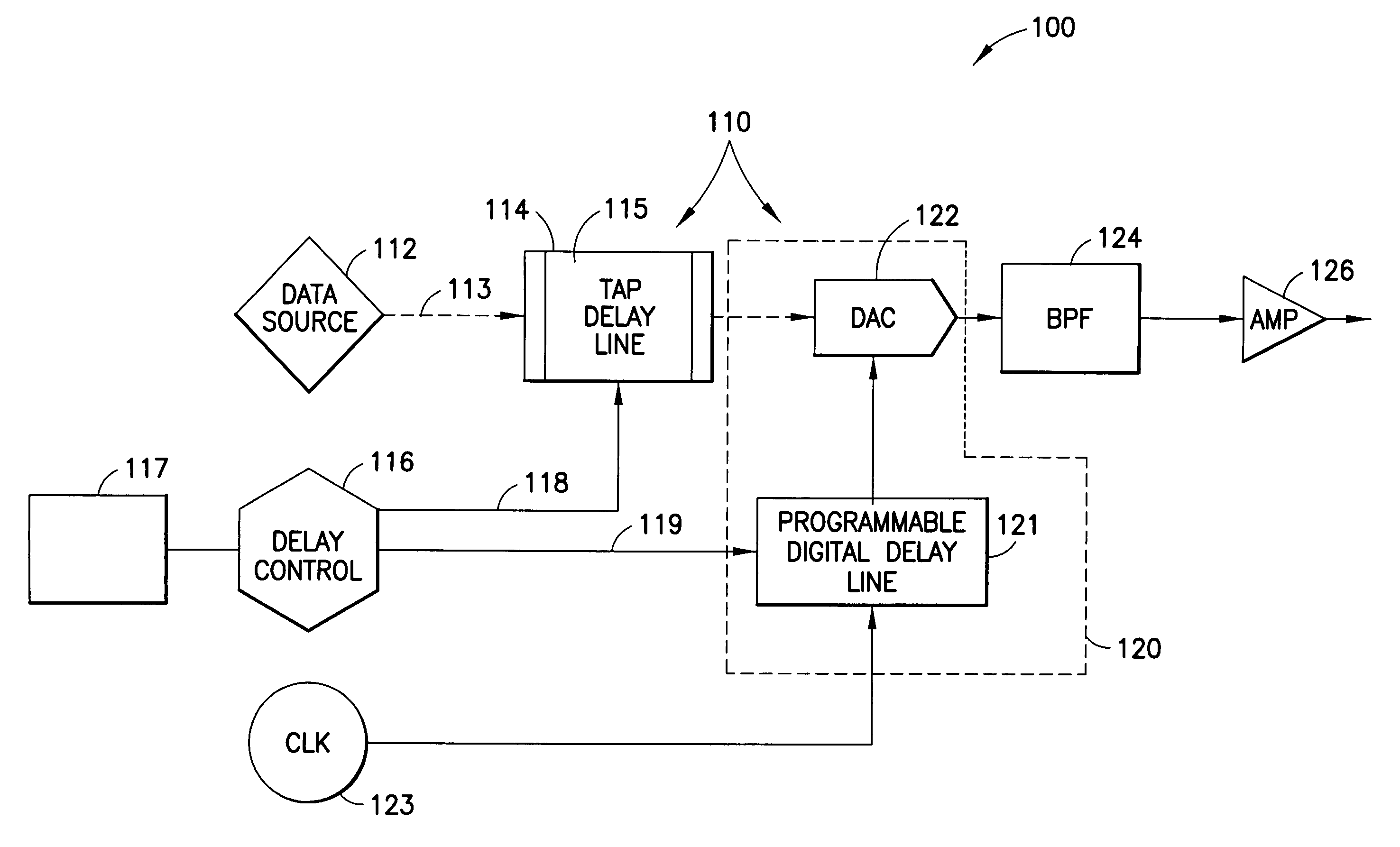
[0014]the present invention comprises a time delay circuit for imparting a time delay to a data signal associated with an antenna element in a multi-element antenna, the time delay circuit comprising: a data signal input for accepting the data signal to be delayed by the time delay circuit; a digital clock reference; a memory storing beamforming control information, wherein the beamforming control information determines physical characteristics of a beam to be formed by the multi-element antenna; a delay control coupled to the memory, where the delay control calculates the time delay to be applied to the data signal in dependence on the beamforming control information, wherein the time delay calculated by the delay control comprises a coarse delay control component expressed in terms of a number of whole clock cycles of the digital clock reference and a fine delay control component expressed in terms of a portion of a whole clock cycle of the digital clock reference, the delay contr...

second embodiment

[0015]the present invention comprises a time delay circuit for imparting a time delay to a signal associated with an antenna element in a multi-element antenna, the time-delay circuit comprising: a signal input for accepting the signal to be delayed by the time delay circuit; digital clock reference means for providing a digital clock reference signal; memory means for storing beamforming control information, wherein the beamforming control information determines physical characteristics of a beam formed by the multi-element antenna; delay control means coupled to the memory means for calculating the time delay to be applied to the signal in dependence on the beamforming control information, wherein the time delay calculated by the delay control means comprises a coarse delay control component expressed in terms of a number of whole clock cycles of the digital clock reference means and a fine delay control component expressed in terms of a portion of a whole clock cycle of the digit...

third embodiment

[0016]the present invention comprises a beamforming network for imparting time delays to a plurality of signals, where each signal is associated with a particular antenna element of a multi-element antenna, wherein the beamforming network further comprises: a digital clock reference; a memory storing beamforming control information, wherein the beamforming control information determines physical characteristics of a beam formed by the combination of the beamforming network and the multi-element antenna; a delay control coupled to the memory, where the delay control calculates the time delay to be applied to each of the plurality of signals in dependence on the beamforming control information, wherein the time delay calculated for each of the signals comprises a coarse delay control component expressed in terms of a number of whole clock cycles of the digital clock reference and a fine delay control component expressed in terms of a portion of a whole clock cycle of the digital clock...


PUM


Abstract

The present invention concerns methods and apparatus for implementing a true-time-delay wideband digital beamformer. In true-time-delay wideband digital beamformers of the present invention, improved control over beam properties formed by the combination of the beamformer and a multi-element antenna coupled to the beamformer is achieved through finer control of delays imparted to data signals. In beamformers of the present invention, data is delayed using a coarse control that provides a delay in whole increments of a clock cycle of a digital clock reference and a fine control that provides a delay corresponding to a fraction of a whole clock cycle of the digital clock reference. In the true time delay method of the present invention, transmission and reception across a wide frequency band is accommodated. In the true time delay method of the present invention, multiple simultaneous beams are formed independently, beam-to-beam, across a wide frequency band.

Description

TECHNICAL FIELD[0001]The present invention generally concerns digital beamforming systems for use in communications systems and more particularly concerns digital true-time-delay wideband beamforming systems having multiple simultaneous beamforming capability.BACKGROUND[0002]Beamforming is a multi-channel array processing method that generates a focused antenna beam electronically, i.e., without the need for physical interaction between a physical aspect of an antenna (such as, for example, a parabolic dish) and an electromagnetic wave. Instead, in antennas comprised of either a linear or a planar two-dimensional array of antenna elements, signals that have been subjected to differing time delays are applied to the antenna elements, thereby focusing the beam formed by the antenna through an electronic process as opposed to a physical process. In essence, a beamformer acts as a spatial band pass filter, amplifying the antenna signal in some directions and attenuating the signal in ot...

Claims


Application Information

Patent Timeline
Patent Type & Authority Patents(United States)
IPC IPC(8): H01Q3/22H01Q3/26
CPCH01Q3/2682H01Q3/26
Inventor JELINEK, CARL O.SMITH, KEITH C.GALLAGHER, FREDKAUFMAN, STEVEN L.FAIRFIELD, DAVID J.
Owner RAYTHEON CO
Learn More