
Polarizer, panel for a liquid crystal display, and liquid crystal display, including a scattering layer

a liquid crystal display and polarizer technology, applied in the direction of polarising elements, instruments, optical elements, etc., can solve the problems of deteriorating display characteristics, color shift, gray inversion, and severe problems of twisted nematic (tn) lcd, so as to minimize gray inversion and eliminate character breaking

Inactive Publication Date: 2008-05-06
SAMSUNG DISPLAY CO LTD
View PDF8 Cites 0 Cited by
  • Summary
  • Abstract
  • Description
  • Claims
  • Application Information

AI Technical Summary

Benefits of technology

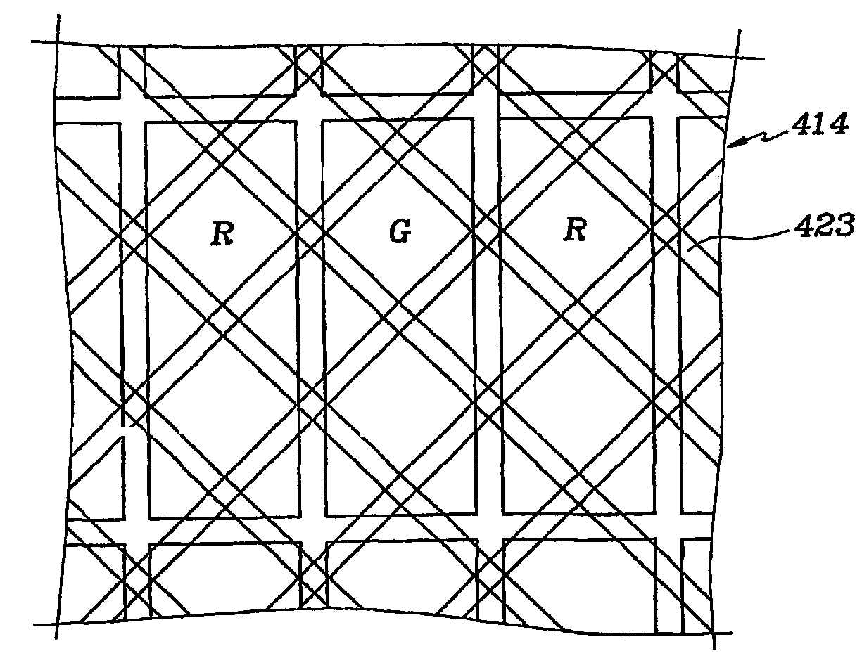
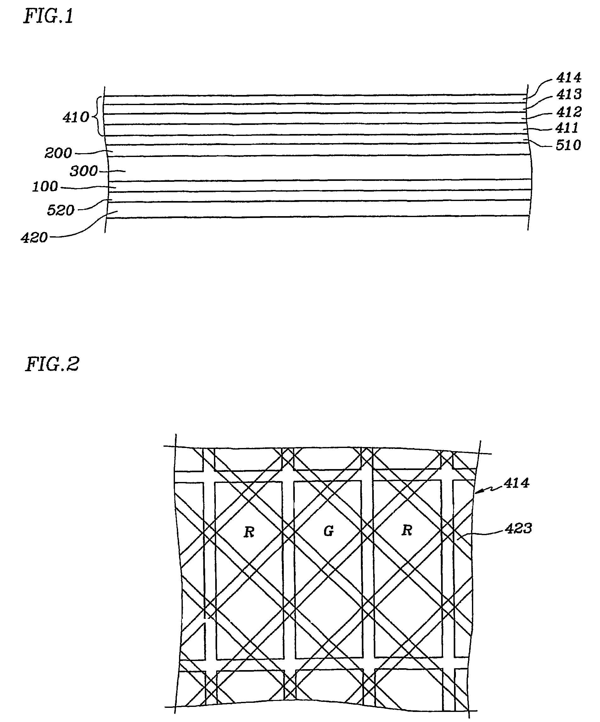
The present invention provides a polarizer, panel for an LCD, and LCD including a scattering layer that can minimize gray inversion and eliminate character breaking. The scattering layer is formed by distributing fillers in a concentration gradient in pixel areas and border areas. The LCD also includes upper and lower polarization plates and a scattering layer may be placed between the second panel and the upper polarization plate, or on the first protective film opposite the analyzer. The fillers are distributed in a net-like pattern and are preferably distributed in a diagonal direction in the pixel areas. The technical effect of the invention is to improve the image quality of LCDs by reducing gray inversion and character breaking.

Problems solved by technology

In particular, a twisted nematic (TN) LCD suffers severe problems such as the contrast ratio depending on the viewing angle, color shift, gray inversion, etc., due to the variation of the retardation of the light.
However, broken characters are generated when haze value indicating the extent of light scattering is high, thereby deteriorating display characteristics.

Method used


Image

  • Polarizer, panel for a liquid crystal display, and liquid crystal display, including a scattering layer
  • Polarizer, panel for a liquid crystal display, and liquid crystal display, including a scattering layer
  • Polarizer, panel for a liquid crystal display, and liquid crystal display, including a scattering layer

Examples


Embodiment Construction

[0017]The present invention now will be described more fully hereinafter with reference to the accompanying drawings, in which preferred embodiments of the invention are shown. This invention may, however, be embodied in many different forms and should not be construed as limited to the embodiments set forth herein.

[0018]In the drawings, the thickness of layers and regions are exaggerated for clarity. Like numerals refer to the elements throughout. It will be understood that when an element such as a layer, film, region, substrate or panel is referred to as being “on” another element, it can be directly on the other element or intervening elements may also be present. In contrast, when an element is referred to as being “directly on” another element, there are no intervening elements present.

[0019]Now, polarizers, panels for an LCD, and LCDs including scattering layers according to embodiments of the present invention are described in detail with reference to accompanying drawings.

[...


PUM

PropertyMeasurementUnit
hazeaaaaaaaaaa
concentrationaaaaaaaaaa
areasaaaaaaaaaa

Abstract

Red, green, blue color filters are arranged in sequence in pixel areas of an LCD according to the present invention. Filters, which are scattering particles of a scattering layer, are distributed in a net, and they are distributed in a diagonal direction such that the concentration of the fillers is lower in border areas located between the pixel areas than in the pixel areas.

Description

BACKGROUND OF THE INVENTION[0001](a) Field of the Invention[0002]The present invention relates to a polarizer, panel for a liquid crystal display, and liquid crystal display including a scattering layer.[0003](b) Description of Related Art[0004]A liquid crystal display (LCD) includes a lower panel provided with thin film transistors (TFTs), etc., an upper panel provided with color filters and a blade matrix, etc., and a liquid crystal layer interposed therebetween. A plurality of pixel electrodes and a common electrode are formed on the respective panels or on a single panel and supplied with voltages. The LCD varies the voltages applied to the pixel electrodes and the common electrode to change the orientations of liquid crystal molecules. In this way, the LCD adjust the transmittance of light and displays images.[0005]The liquid crystal material of an LCD has birefringence that the refractive indices in a direction of molecular long axes and in a direction of molecular short axes ...

Claims


Application Information

Patent Timeline
Patent Type & Authority Patents(United States)
IPC IPC(8): G02F1/1335G02B5/02G02B5/30G02F1/1333
CPCG02B5/0226G02F1/133504G02B5/3041G02B5/0242G02F1/1335
Inventor SONG, YOUNG-GOOHONG, KWEON-SAMLEE, HAN-JUUM, YOON-SUNG
Owner SAMSUNG DISPLAY CO LTD
Learn More