
Exercise device for foot, ankle and/or shin

a technology for exercising devices and feet, applied in the direction of muscle exercise devices, gymnastic exercise, sport apparatus, etc., can solve the problems of individual's inability to keep their balance, individual at serious risk of suffering a harmful fall, and weakened or atrophied

Inactive Publication Date: 2008-04-29
ROBERT GREGORY ZOLLER
View PDF50 Cites 40 Cited by
  • Summary
  • Abstract
  • Description
  • Claims
  • Application Information

AI Technical Summary

Benefits of technology

[0015]The exercise device of this invention provides a number of benefits for the user thereof. This device allows for resisted movement of the ankle joint through the full range of motion, including dorsiflexion, plantarflexion, adductor and abductor, and in any particularly desired combination of such motions. In particular, this device provides strengthening and / or rehabilitation of the muscles and tendons in the foot and lower leg, especially those of the shin, as well as the anterior portion of the foot and lower leg. The device can accommodate differing foot sizes of various users, and is easily adjustable to change the degree of resisted pivotal movement to meet the exercise and strength needs of the user.

Problems solved by technology

Because the ankle joint supports the entire weight of the body during upright movement, it is, at times, subjected to severe stresses that can cause injury.
This, in turn, compromises the individual's ability to keep their balance and places the individual at serious risk of suffering a harmful fall.
In fact, the muscles, ligaments, and tendons of the joint are often immobilized for a sufficient period of time thereby causing them to become weakened or atrophied.
Indeed, a frequently neglected muscle group for exercise injury prevention and rehabilitation is the shin.
Moreover, by strengthening the muscles in the lower leg and foot, one may significantly reduce the possibility of future ankle injuries.
As a result, these prior devices do not provide, for example, all of the dorsiflexion and plantarflexion motion, coupled with adductor and abductor motion necessary to exercise of the ankle throughout the full range of motion.
Many of these prior exercise or rehabilitation devices involve rocking on a ball-type joint and thus provide little, if any, resistance to movement of the ankle through its full range of motion.

Method used


Image

  • Exercise device for foot, ankle and/or shin
  • Exercise device for foot, ankle and/or shin
  • Exercise device for foot, ankle and/or shin

Examples


Embodiment Construction

[0021]As used herein, the term “comprising” means various components, steps and the like can be conjointly employed in this invention. Accordingly, the term “comprising” encompasses the more restrictive terms “consisting essentially of” and “consisting of.”

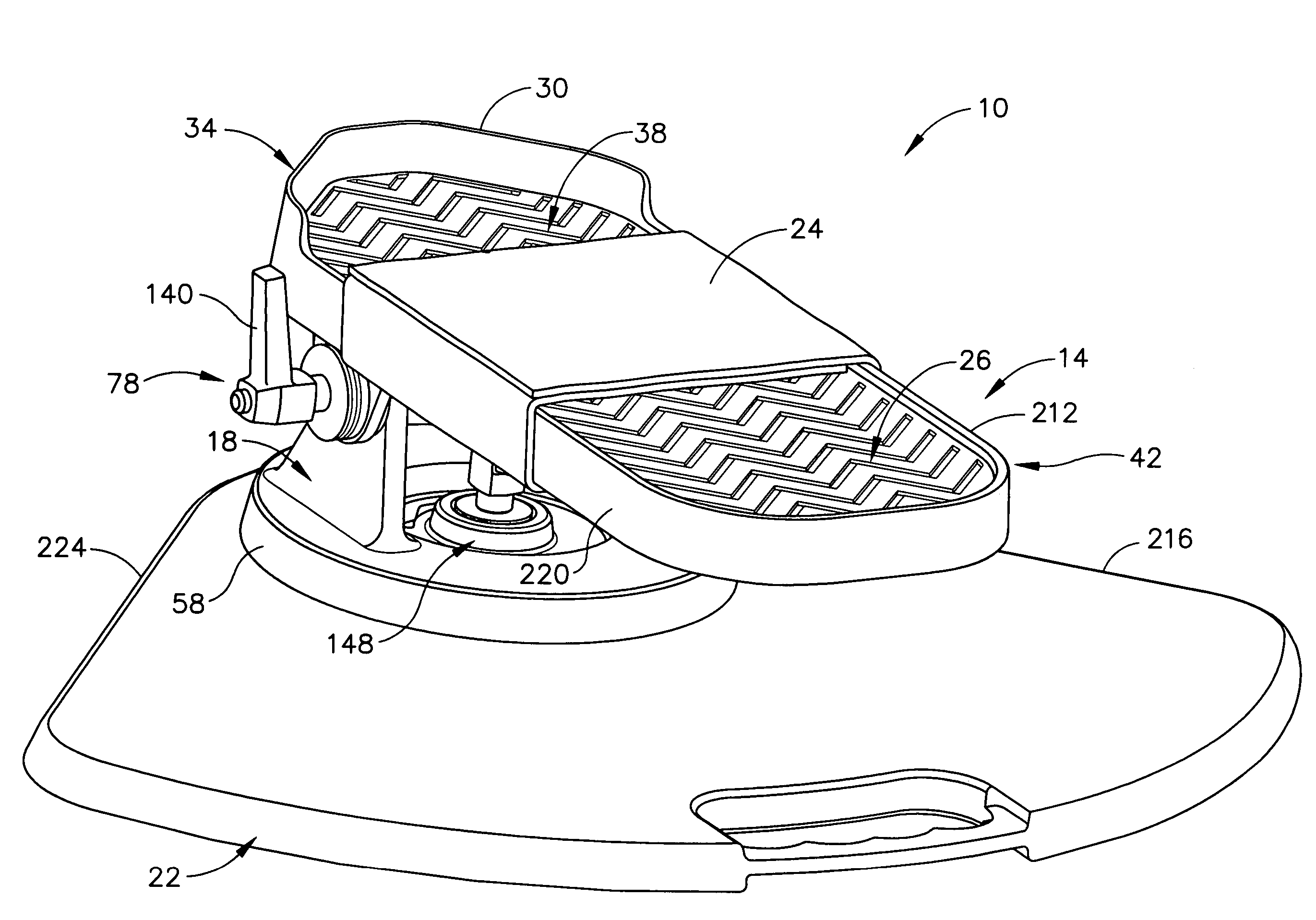
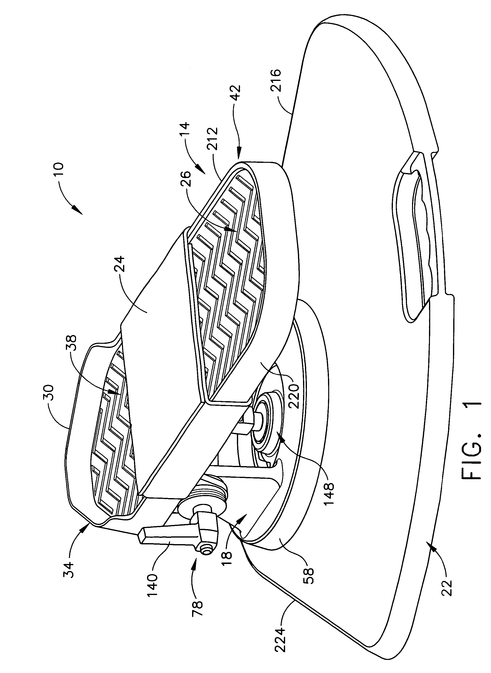
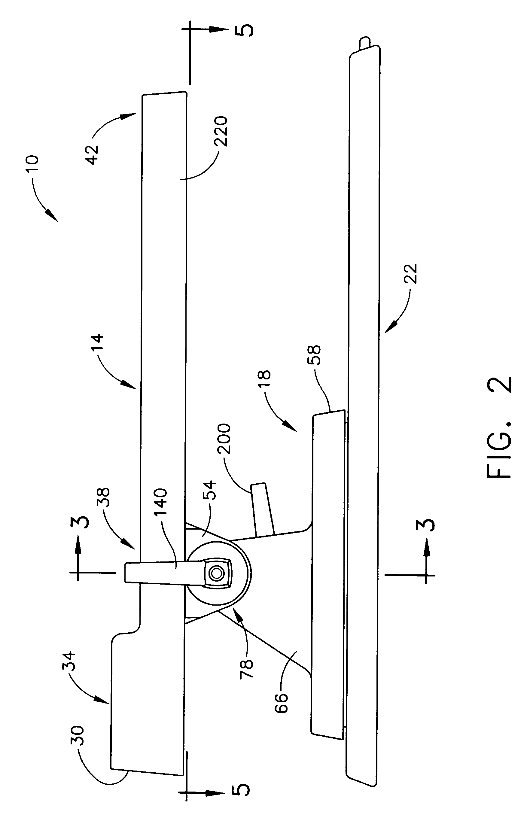
[0022]The various embodiments of this invention are further illustrated by reference to the drawings as described hereafter. Referring to the drawings, FIG. 1 shows an embodiment of the exercise device generally indicated as 10. Exercise device 10 generally comprises a foot receiving member in the form of a foot pad indicated generally as 14, a mount member in the form of a mounting bracketing indicated generally as 18, and a base member indicated generally as 22. The user places their foot in or on foot pad 14, the user's foot then being releasably secured to foot pad 14 by a foot securing member, such as an adjustable velcro type-strap indicated generally as 24 that is typically attached or secured underneath foot pad 14. Foot p...


PUM


Abstract

An exercise device for providing resisted movement of the ankle through the full range of motion thereof to exercise the muscles in the ankle, foot, lower leg and especially shin area. This exercise device comprises: (a) a base; and (b) a foot receiving member having an ankle section. The foot receiving member is mounted on the base for resisted pivotal movement about: (1) a substantially horizontal axis extending transversely and underneath the ankle section of the foot receiving member; and (2) a substantially vertical axis extending from the base and through the ankle section of the foot receiving member.

Description

TECHNICAL FIELD[0001]This invention relates to an exercise device for strengthening muscles in the foot, ankle and lower leg, especially the shin.BACKGROUND OF THE INVENTION[0002]The human ankle joint is capable of a wide range of motion. Such motion includes dorsiflexion (moving the foot upwardly), plantarflexion (moving the foot downwardly), adductor (moving the foot inwardly toward the midline of the body) and abductor (moving the foot outwardly away from the midline of the body). Because the ankle joint supports the entire weight of the body during upright movement, it is, at times, subjected to severe stresses that can cause injury. This can occur while working, while performing day-to-day activities and especially during athletic activity. Due to such circumstances, ankle joint injuries are among the most common injuries suffered.[0003]Moreover, the ankle joint plays an important role in maintaining balance. As individuals age and / or deteriorate due to disease, the ankle joint...

Claims


Application Information

Patent Timeline
Patent Type & Authority Patents(United States)
IPC IPC(8): A63B23/08A63B21/015A63B23/10
CPCA63B23/08A63B21/015
Inventor ZOLLER, ROBERT GREGORYHONERKAMP, ANTHONY JOSEPH
Owner ROBERT GREGORY ZOLLER
Learn More