
Front harvesting attachment

a front and attachment technology, applied in the field of front harvesting attachments, can solve the problems of inability to forget or overlook the locking position of the front harvesting attachment, the attachment will inadvertently not be locked, and the relative high cost, so as to prevent oscillating movement

Active Publication Date: 2008-04-22
MASCHFAB KEMPER +1
View PDF19 Cites 41 Cited by
  • Summary
  • Abstract
  • Description
  • Claims
  • Application Information

AI Technical Summary

Benefits of technology

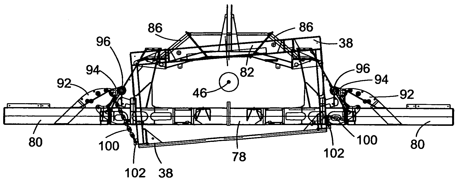
[0008]Immobilizing devices prevent oscillating movement of the front harvesting attachment relative to the intake channel during transportation. Adjusting devices pivot the side parts between the operating position and the transport position, and simultaneously, activate the immobilizing devices.
[0009]In this way the front harvesting attachment is held stationary relative to the intake channel when the side parts are located in the transport position. In addition the immobilizing devices are released automatically when the side parts are moved to the operating position. It is not possible to move the side parts to the transport position without activating the immobilizing devices, therefore, locking the front harvesting attachment in position cannot be forgotten or overlooked.

Problems solved by technology

Here a separate hydraulic cylinder is provided to immobilize the front harvesting attachment, resulting in a relatively high cost.
There is also the danger that the attachment will inadvertently not be locked before operation on public roads.
It is not possible to move the side parts to the transport position without activating the immobilizing devices, therefore, locking the front harvesting attachment in position cannot be forgotten or overlooked.

Method used


Image

  • Front harvesting attachment
  • Front harvesting attachment
  • Front harvesting attachment

Examples


Embodiment Construction

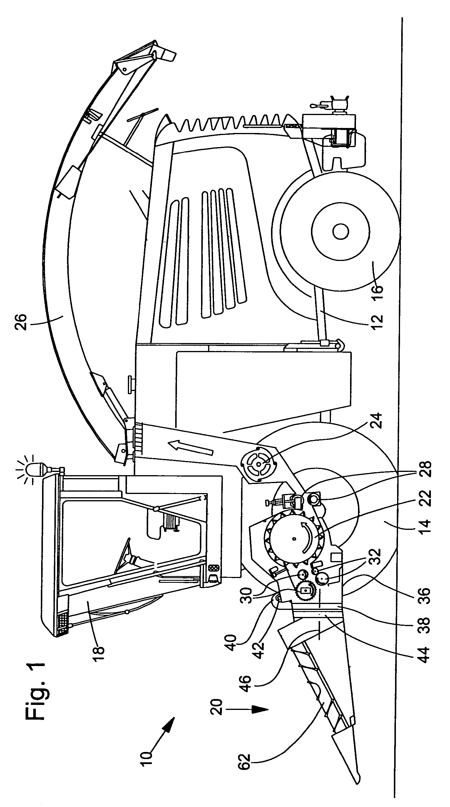
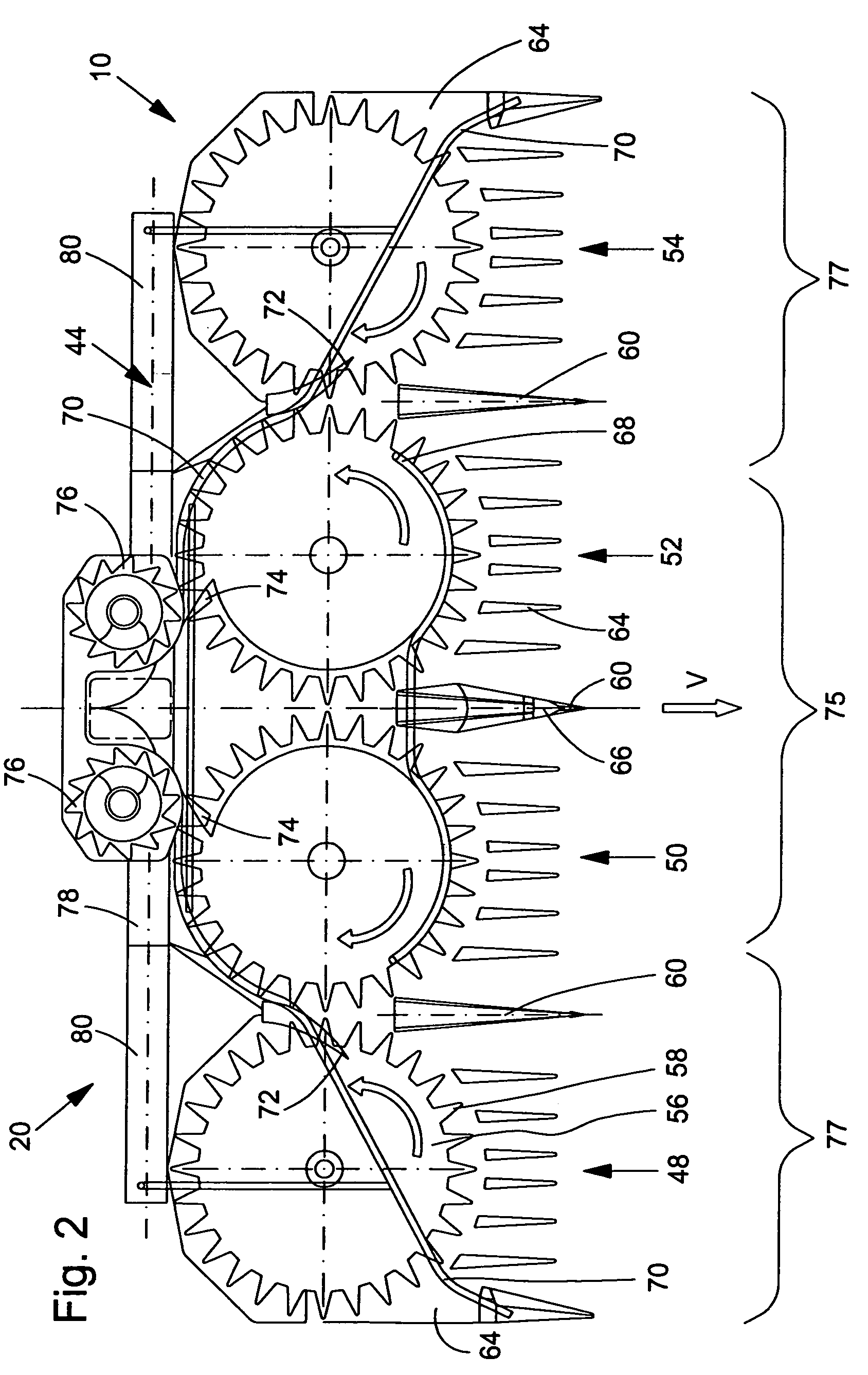
[0019]Referring to FIG. 1, a harvesting machine having a front attachment and embodying the principles of the present invention is generally shown and designated at 10. The self-propelled forage harvester 10 is supported on a frame 12 that is carried by driven front wheels 14 and steerable rear wheels 16. The operation of the harvesting machine 10 is controlled from an operator's cab 18 from which a front harvesting attachment 20, appropriate for the harvest of stalk like plants, can be controlled visually. Crop taken up from the ground by means of the front harvesting attachment 20, for example corn, cereal crop or the like, is conducted to a chopper drum 22 by means of upper rough pressing rolls 30 and lower rough pressing rolls 32. The chopper drum 22 chops the crop into small pieces and delivers it to a conveyor assembly 24. As shown, the front harvesting attachment 20 is a corn head that operates independently of rows. The crop leaves the harvesting machine 10 to an accompanyin...


PUM


Abstract

A front harvesting attachment for a self-propelled harvesting machine having a central part pivotally mounted onto an intake channel of the harvesting machine, side parts that are moveable relative to the central part between an operating position, wherein the side parts are positioned on either side of the central part, and a raised transport position. Adjusting devices move the side parts between the operation and raised transport positions. Immobilizing devices selectively prevent movement of the front harvesting attachment relative to the intake channel during transport of the harvesting attachment. The immobilizing devices are coupled to the adjusting devices such that the immobilizing devices are actuated, thereby preventing movement of the front harvesting attachment relative to the intake channel, when the adjusting devices have moved the side parts to the raised transport position.

Description

FIELD OF THE INVENTION[0001]The invention concerns a front harvesting attachment for a self-propelled harvesting machine with a center and side parts that are pivotally mounted to an intake channel of a harvesting machine.BACKGROUND OF THE INVENTION[0002]Prior agricultural mowing machines include a vehicle with several mowing units arranged to the side of the vehicle and alongside each other. The vehicle includes a carrier extending transverse to the direction of operation onto which a first mowing unit is fastened. A second, outer mowing unit is pivotally fastened to the carrier. The mowing units can be brought into a non-operating position, wherein the carrier is pivoted upward by a hydraulic cylinder, about an axis aligned with the direction of operation relative to the harvesting machine. This movement carries the first mowing unit, while simultaneously, the second mowing unit is pivoted inward, by a second hydraulic cylinder, about an axis extending in the direction of operatio...

Claims


Application Information

Patent Timeline
Patent Type & Authority Patents(United States)
IPC IPC(8): A01B73/00
CPCA01D41/144
Inventor RICKERT, CLEMENSHUNING, MARTINHOCKENBECK, LEO SCHULZEWEITENBERG, KLEMENS
Owner MASCHFAB KEMPER
Learn More