
Hybrid type double three-phase electric rotating machine

a technology of electric rotating machines and hybrids, applied in dynamo-electric machines, instruments, horology, etc., can solve the problems of large noise and large vibration under operation, and achieve the effect of reducing cogging torqu

Inactive Publication Date: 2008-03-11
JAPAN SERVO CO LTD
View PDF26 Cites 10 Cited by
  • Summary
  • Abstract
  • Description
  • Claims
  • Application Information

AI Technical Summary

Benefits of technology

The present invention provides a hybrid type complex three-phase electric rotating machine that reduces cogging torque while keeping the resolution of a conventional double three-phase motor. The machine includes a stator core with stator poles, coils wound around the stator poles, and a rotor with a permanent magnet. The coils are connected so that a pair of stator poles are excited in opposite polarities when the number of stator poles is twelve, or alternately when the number is twenty-four. The angle between inductors at the corresponding positions of adjacent stator poles satisfies certain conditions to reduce cogging torque. The machine can be used as a stepping motor or a multi-pole brushless DC motor with high resolution and low cogging torque.

Problems solved by technology

Though the double three-phase stepping motor disclosed in the patent gazette has high resolution, cogging torque generated by the permanent magnet of the rotor when the coils are not excited becomes large, which causes large vibration and large noise under operation.

Method used


Image

  • Hybrid type double three-phase electric rotating machine
  • Hybrid type double three-phase electric rotating machine
  • Hybrid type double three-phase electric rotating machine

Examples


Embodiment Construction

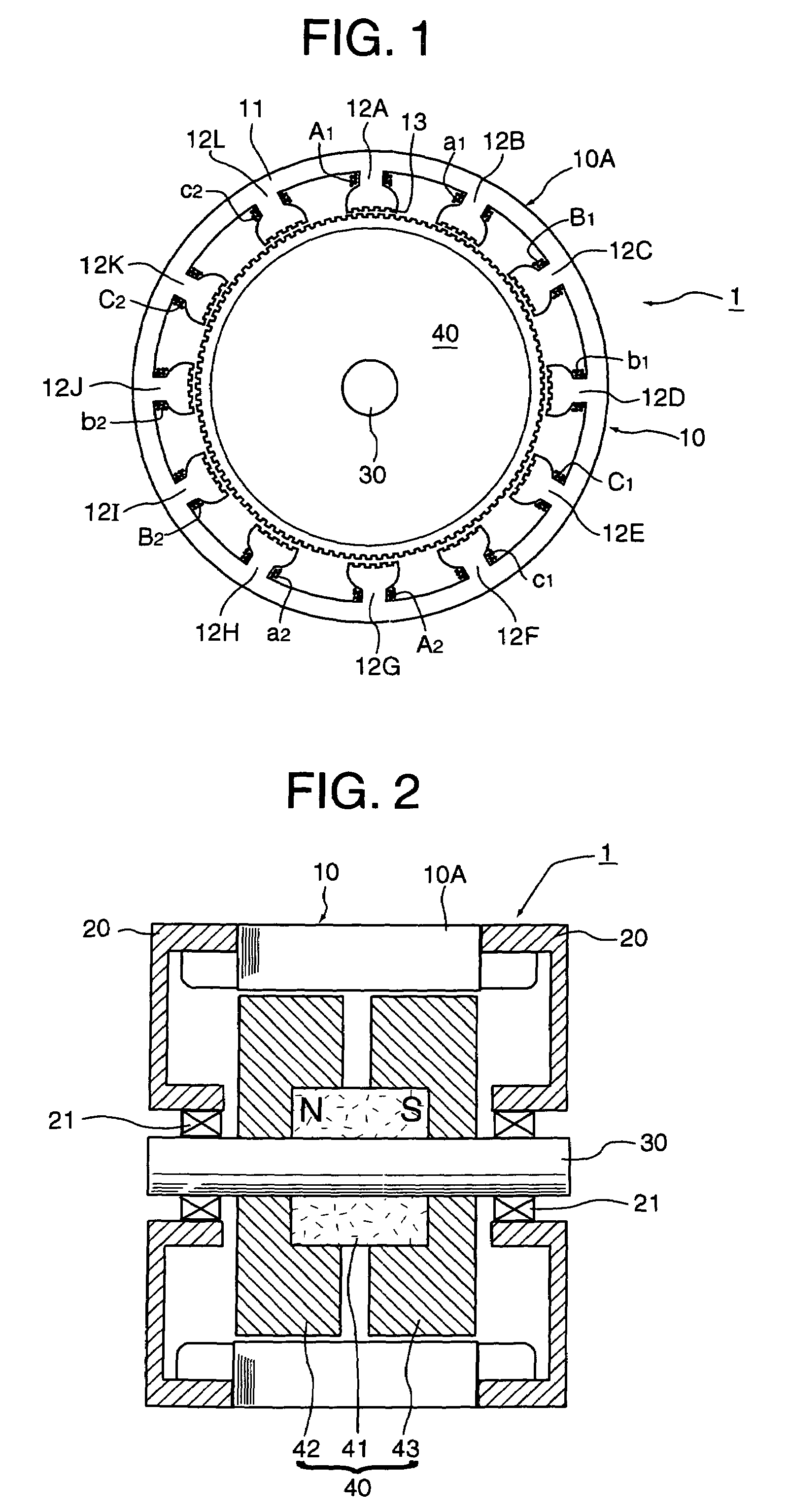
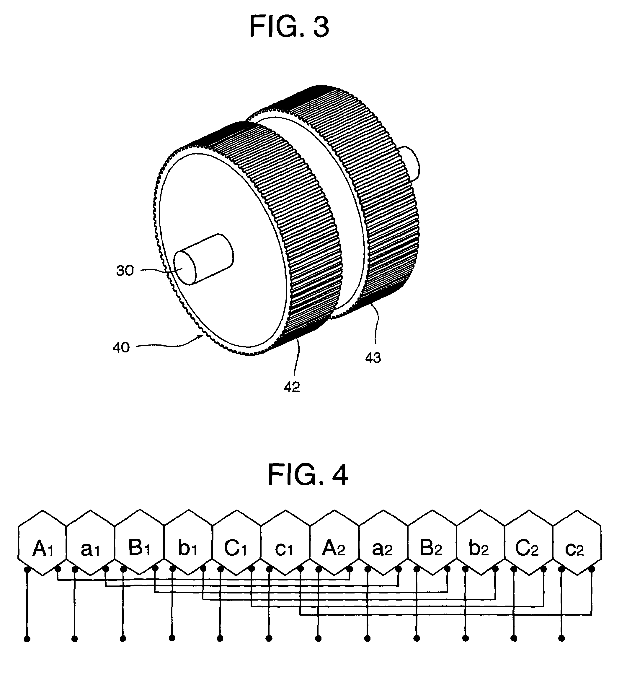
[0036]Hereinafter, a hybrid type double three-phase stepping motor will be described as an embodiment of the hybrid complex three-phase electric rotating machine of the present invention with reference to the drawings. FIG. 1 through FIG. 3 show a basic construction of the hybrid type double three-phase stepping motor, FIG. 1 is a section view in a plane perpendicular to the rotation axis, FIG. 2 is a section view in a plane parallel to the rotation axis, and FIG. 3 is a perspective view of a rotor.

[0037]The hybrid type double three-phase stepping motor 1 of the embodiment is an inner rotor type having twelve stator poles and is provided with a cylindrical-shaped stator 10, a pair of end brackets 20, 20 that are fixed to the both ends in the axial direction of the stator, a rotating shaft 30 that is rotatably supported by bearings 21, 21 mounted on the centers of the respective end brackets 20, 20, and a hybrid type rotor 40 fixed to the rotating shaft 30 to rotate with the shaft 30...


PUM


Abstract

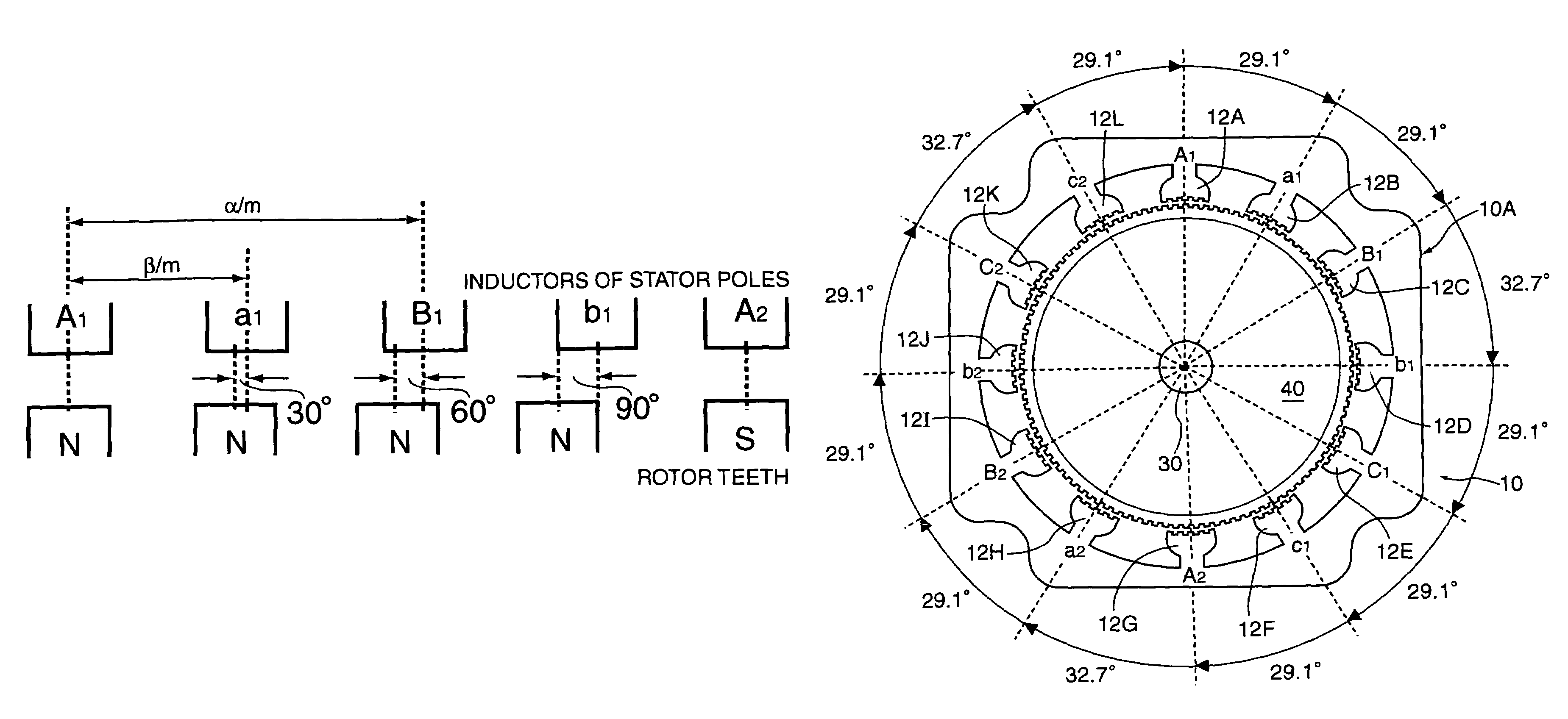
A stator core having twelve stator poles, coils wound around the stator poles, and a hybrid type rotor are included. The stator poles inwardly and radially extended from an annular yoke portion. Each of the respective stator poles has the same number of inductors. The coils are connected so that a pair of the stator poles being substantially symmetric with respect to a point are excited in opposite polarities. The rotor is arranged with a predetermined air gap with respect to the inductors, the rotor has a pair of rotor cores each of which has rotor teeth facing to the inductors and a permanent magnet magnetized in the axial direction sandwiched therebetween. The angles between inductors at the corresponding positions of adjacent stator poles are defined by repeating three sets of angular distributions each of which includes three times of 29.1 degrees and one time of 32.7 degrees when a number of rotor teeth equals 100.

Description

BACKGROUND OF THE INVENTION[0001]The present invention relates to an electric rotating machine such as a stepping motor used in OA (Office Automation) equipment or the like. Specifically, the present invention relates to a hybrid type double three-phase electric rotating machine.[0002]An electric rotating machine such as a stepping motor that has a high positioning accuracy and low vibration is required in a use of OA equipment or the like. Japanese patent gazette No. 3537904 (JP 3537904B) discloses a double three-phase stepping motor that has two sets of three-phase coils. The motor is high in resolution, suitable for a use of positioning and low in cost.[0003]FIG. 9 is a section view in a direction perpendicular to a rotation axis of the stepping motor shown in the patent gazette. The motor 2 disclosed in the patent gazette is provided with a stator 3 that has twelve stator poles 3b extended inwardly and radially from a cylindrical-shaped yoke portion 3a and a rotor 4 arranged ins...

Claims


Application Information

Patent Timeline
Patent Type & Authority Patents(United States)
IPC IPC(8): H02K37/14
CPCH02K37/18
Inventor SAKAMOTO, MASAFUMITOZUNE, AKIRA
Owner JAPAN SERVO CO LTD
Learn More