
Carriage for a collapsible reformer exercise apparatus

a technology of movable carriage and reformer, which is applied in the direction of resilient force resistors, gymnastics exercises,stilts, etc., can solve the problems of complex carriages, inconvenient manufacture, and inability to adapt to the needs of the available reformer

Active Publication Date: 2007-11-13
BALANCED BODY INC
View PDF8 Cites 45 Cited by
  • Summary
  • Abstract
  • Description
  • Claims
  • Application Information

AI Technical Summary

Problems solved by technology

One of the difficulties, which the currently available reformers do not optimally address, is the portability and storability of the apparatus.
However, this reformer has a carriage that is complex to manufacture.

Method used


Image

  • Carriage for a collapsible reformer exercise apparatus
  • Carriage for a collapsible reformer exercise apparatus
  • Carriage for a collapsible reformer exercise apparatus

Examples


Embodiment Construction

[0019]A reformer exercise apparatus 100 in accordance with an embodiment of the present invention is shown in upper and lower perspective views in FIGS. 5 and 6 respectively. In these two views, the telescopic frame 102 of the reformer 100 is shown collapsed rather than fully extended. The frame 102 has a head end 104 and a foot end 106 and a pair of parallel track or rail member assemblies 108 separating the head end 104 from the foot end 106.

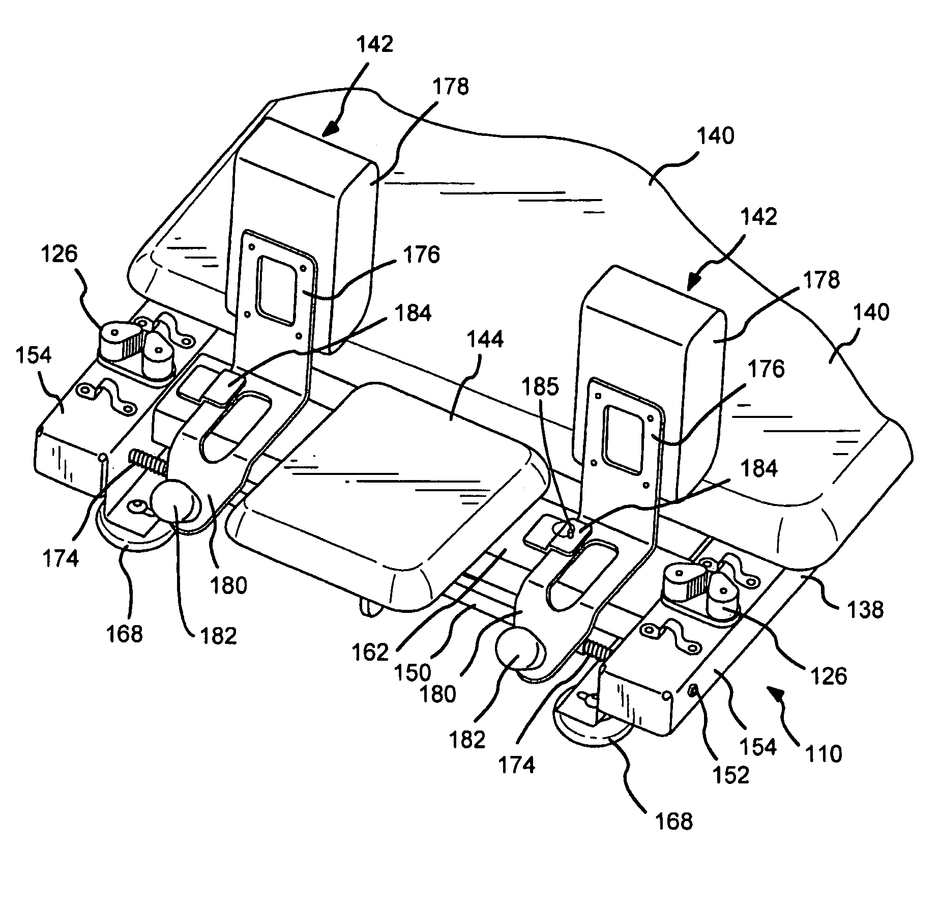
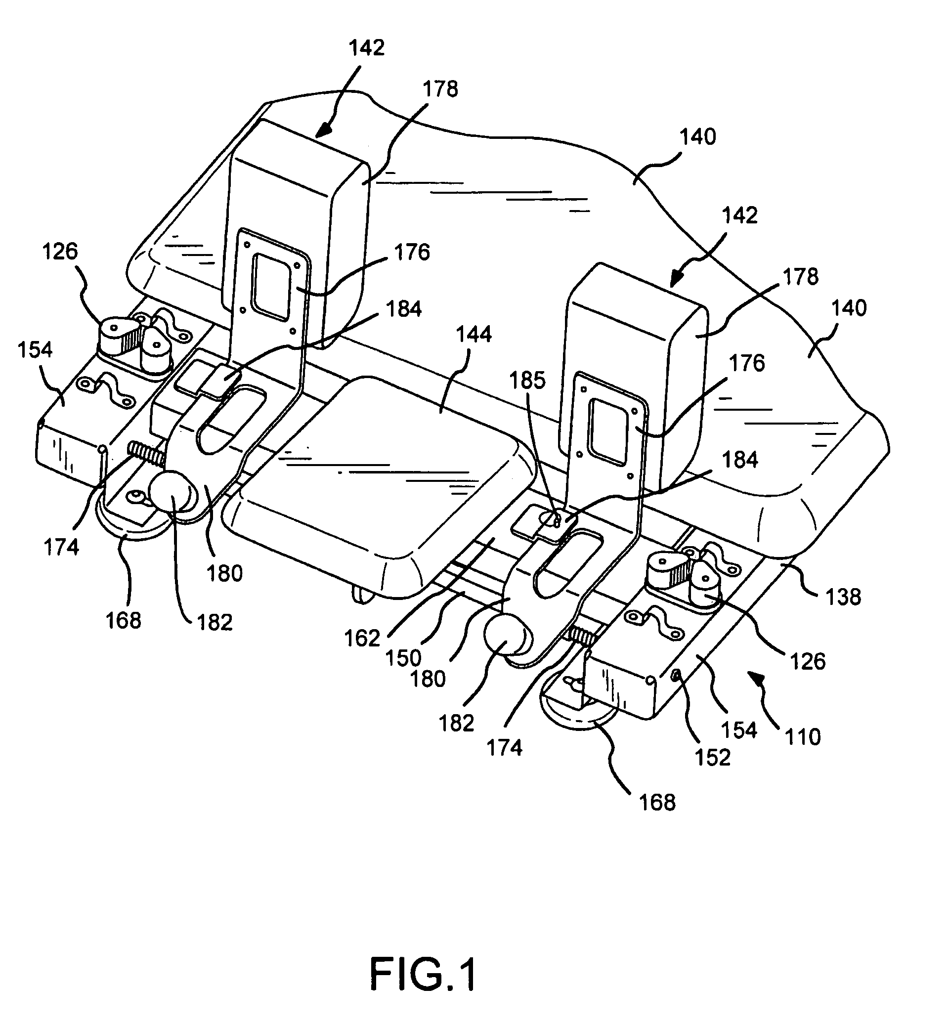
[0020]A movable carriage assembly 110 in accordance with an embodiment of the present invention is shown in partial perspective views in FIGS. 1 through 4. The carriage assembly 110 includes four roller wheels 112 (shown in FIGS. 3 and 7) fastened to the underside of the carriage 110. The roller wheels 112 roll on the track member assemblies 108 to support and guide movement of the carriage 110 back and forth along the track member assemblies 108 of the frame 102. Up to seven elastic members, e.g., springs 114, shown in FIGS. 5, 6, and 7, may ...


PUM


Abstract

A carriage for use in a reformer exercise apparatus is disclosed that has a pair of upwardly extending folding shoulder stops mounted thereto at one end and a headrest between the shoulder stops that extends outward from the carriage toward the head end of the frame. A pair of roller wheels at the head end and a pair at the foot end of the carriage support the platform. A single common axle supports the head end pair of rollers from the carriage, forms a pivot support for the folding shoulder stops, and forms part of an adjustable position support assembly for the headrest. The shoulder stops are preferably attached to a tubular sleeve that rotates on the common axle.

Description

CROSS REFERENCE TO RELATED APPLICATIONS[0001]This application is related to U.S. patent application Ser. No. 10 / 035,842 filed Dec. 24, 2001, publication No. US-2002-0058573-A1, which is hereby incorporated by reference in its entirety.BACKGROUND OF THE INVENTION[0002]1. Field of the Invention[0003]This invention relates generally to the field of exercise equipment in which a movable carriage is utilized to at least partially support a user's body, commonly referred to as a “reformer”, and more particularly to a telescopically collapsible reformer with a compact movable carriage.[0004]2. Description of the Related Art[0005]Joseph H. Pilates, in U.S. Pat. No. 1,621,477, originally developed the concept of using a wheeled platform carriage connected to a resistance device such as a set of weights in conjunction with a stationary frame to provide a variable resistance against which a user could push with his / her feet or pull with the arms while in a sitting or recumbent position in orde...

Claims


Application Information

Patent Timeline
Patent Type & Authority Patents(United States)
IPC IPC(8): A63B26/00
CPCA63B22/0007A63B22/001A63B22/203A63B22/0087A63B21/00065A63B21/023A63B21/0428A63B2208/0204A63B2208/0257A63B2210/50A63B2225/093
Inventor BARNARD, EDWARD D.ENDELMAN, KEN
Owner BALANCED BODY INC
Learn More