
Body vibrating facility

a body and facility technology, applied in the field of body vibrating facilities, can solve the problems of limited movement speed of the vibrating plate by the threaded shaft and the motorized rotary gear, the inability to use the vibrating plate and the users, and the chance of users being hurt, so as to facilitate the blood and/or lymph circulation and reduce the fat from the user

Inactive Publication Date: 2007-10-09
LIN MICHAEL
View PDF7 Cites 20 Cited by
  • Summary
  • Abstract
  • Description
  • Claims
  • Application Information

AI Technical Summary

Benefits of technology

"The present invention is a body vibrating facility that can stably support a user and vibrate their body. It includes a base, two plates, two rods, two followers, a link, foot supports, a reduction gearing device, and a motor. The motor can rotate and vibrate the followers, rods, and foot supports. The foot supports are stably supported and driven or vibrated by the motor. The reduction gearing device allows for easy rotation and driving of the followers, rods, and foot supports. The facility also includes a housing for protection. The technical effects of the invention include improved blood and lymph circulation, reduction of body fat, and improved stability and comfort for users."

Problems solved by technology

However, the magnetic field and the magnetic force generated by the hollow vibrating facility coil and the armatures are not good for the users and may have a good chance to hurt the users, particularly the nerve systems of the users.
However, the moving speed of the vibrating plate by the threaded shaft and the motorized rotary gear is limited and may not be used to vibrate the vibrating plate and the users.

Method used


Image

  • Body vibrating facility
  • Body vibrating facility
  • Body vibrating facility

Examples


Embodiment Construction

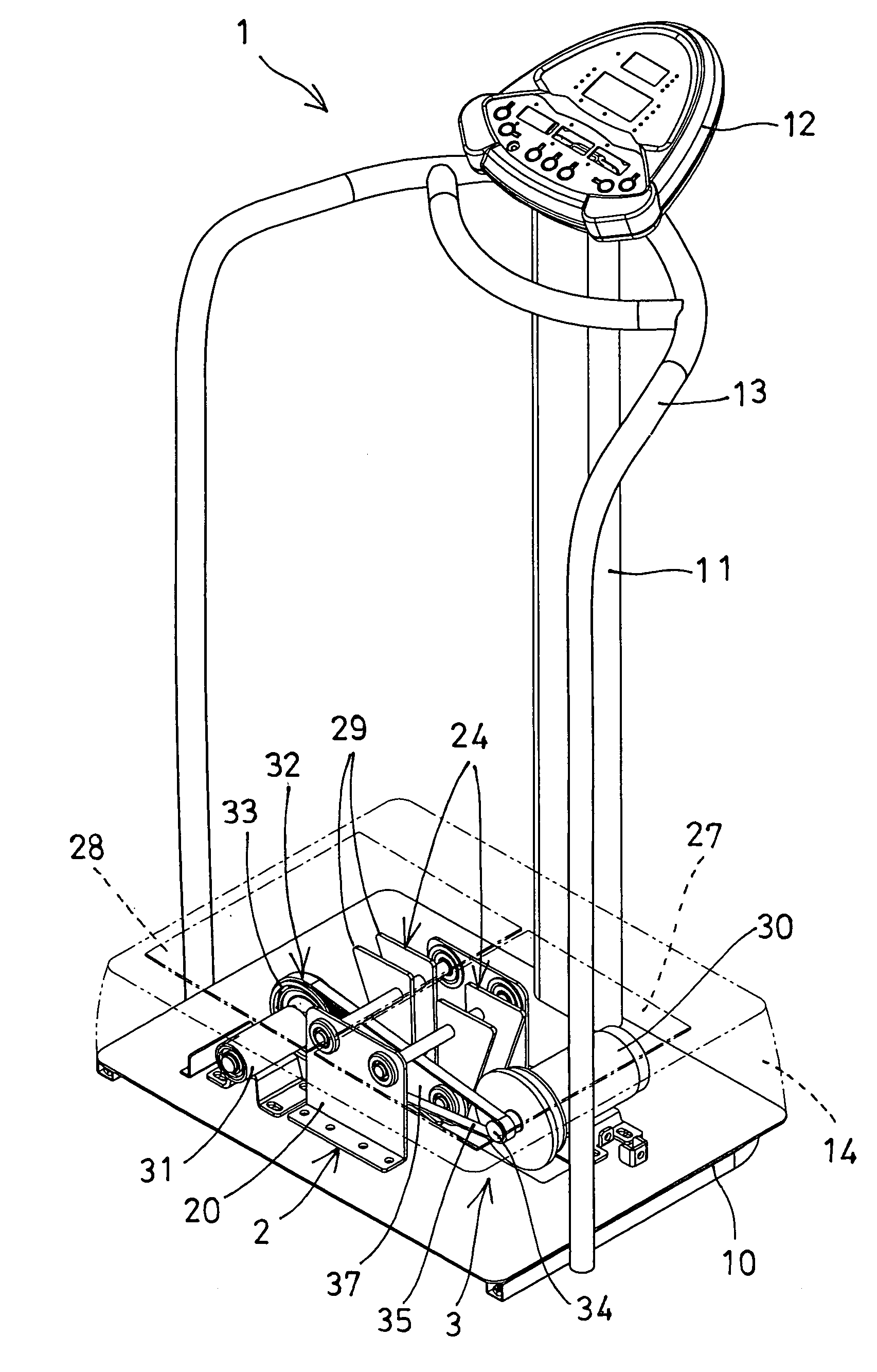
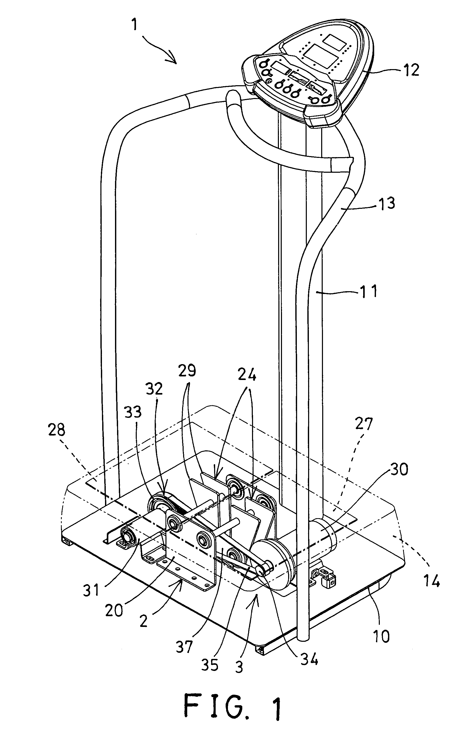
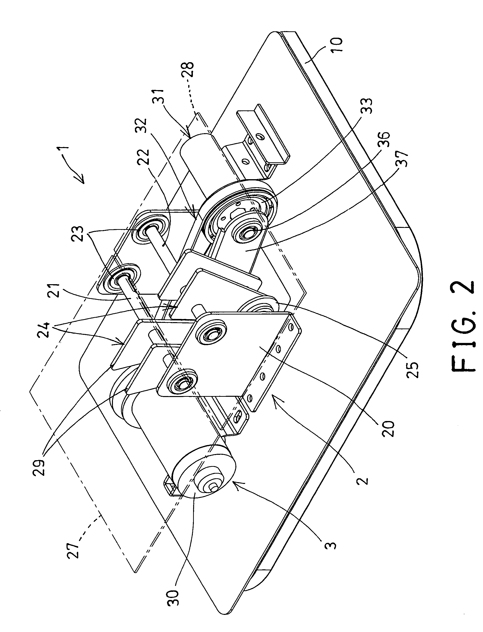
[0024]Referring to the drawings, and initially to FIGS. 1-4, a body vibrating facility 1 in accordance with the present invention comprises a base 10 for supporting a support device 2 and a vibrating device 3 thereon, and including a post 11 extended upwardly therefrom, such as extended upwardly from the front portion thereof for supporting a displayer or control device 12 thereon, and including one or more handle devices 13 disposed thereon and / or attached or coupled to the post 11 for supporting the upper portions of the users, and including a cover or housing 14 engaged or attached onto the base 10 for covering or shielding or protecting the support device 2 and the vibrating device 3 and for preventing the support device 2 and the vibrating device 3 from being exposed.

[0025]The support device 2 includes one or more, such as two plates 20 disposed on the base 10 and spaced away from each other and preferably parallel to each other, two rods 21, 22 rotatably attached or disposed t...


PUM


Abstract

A body vibrating device includes two rods rotatably straddled between two plates, two followers attached to the rods and coupled together with a link, two foot supports attached to the followers, a reduction gearing device disposed on the base and having an eccentric member coupled to either of the followers for allowing the followers and the rods and the foot supports to be rotated and driven by the reduction gearing device, and a motor coupled to the reduction gearing device for driving the reduction gearing device to vibrate the followers and the rods and the foot supports. The foot supports may be stably supported and driven or vibrated by the motor.

Description

BACKGROUND OF THE INVENTION[0001]1. Field of the Invention[0002]The present invention relates to a body vibrating facility, and more particularly to a body vibrating facility including a stable structure for stably supporting a user thereon and for suitably vibrating and massaging the whole user' body and for facilitating the blood and / or lymph circulation of the user and for decomposing or for burning the fatty tissue and thus for suitably reducing the fat from the user.[0003]2. Description of the Prior Art[0004]Various kinds of typical body vibrating facilities have been developed and comprise a platform for supporting the user thereon, and a hollow vibrating facility coil and a pair of armatures provided for vibrating the platform in order to suitably vibrate and massage the user who is standing on the platform.[0005]For example, U.S. Pat. No. 2,271,382 to Worthington discloses one of the typical platform foot and body vibrating facility also comprising one of two armatures attac...

Claims


Application Information

Patent Timeline
Patent Type & Authority Patents(United States)
IPC IPC(8): A61H1/00
CPCA61H1/003A61H1/005A61H2201/5043A61H2201/1635A61H2201/164A61H23/0254
Inventor CHEN, MING NAN
Owner LIN MICHAEL
Learn More