
Locking device support

a technology for locking devices and supports, which is applied to lightening support devices, washstands, scaffold accessories, etc., can solve the problems of vibration or shock-induced forces generally harmful to the device, and the device is easy to be stolen

Active Publication Date: 2007-09-25
CARNEVALI JEFFREY D
View PDF7 Cites 71 Cited by
  • Summary
  • Abstract
  • Description
  • Claims
  • Application Information

AI Technical Summary

Problems solved by technology

In other words, such currently known mounting platforms permit easy theft of the device.
Furthermore, currently known mounting platforms tend to permit the accessory device to slip within the mounting platforms when vibration or shock-induced forces act on the accessory device during motion of the vehicle.
Such vibration or shock-induced forces are generally harmful to the device.

Method used


Image

  • Locking device support
  • Locking device support
  • Locking device support

Examples


Embodiment Construction

[0014]In the Figures, like numerals indicate like elements.

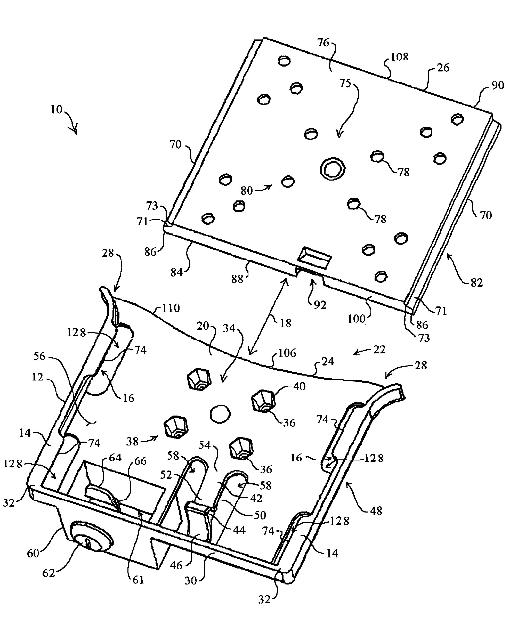
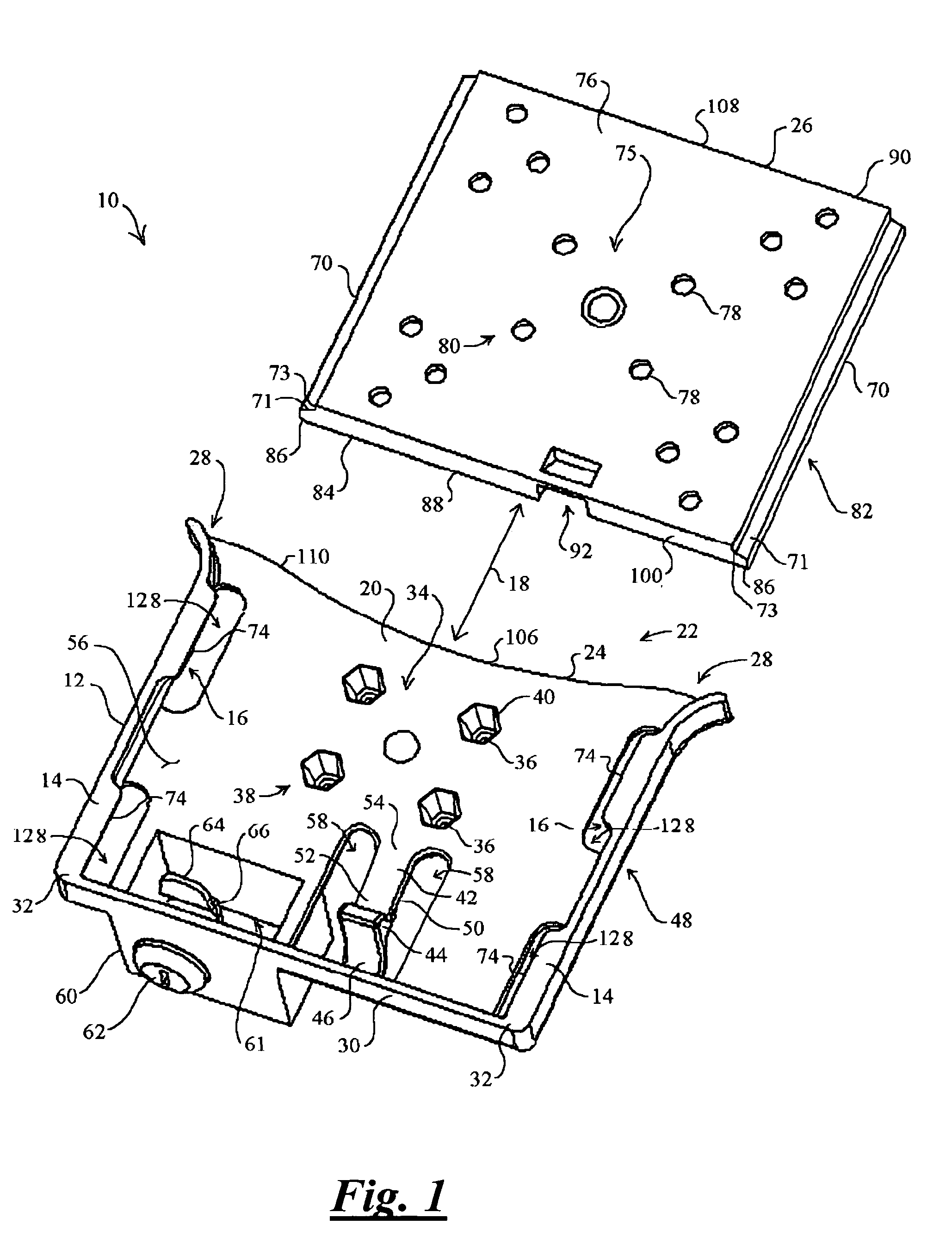
[0015]FIG. 1 is an exploded perspective view that illustrates the invention embodied as an exemplary mounting platform 10 for various vehicle-mounted, after-market accessory devices, such as a portable computer, or another useful accessory device. By example and without limitation, the mounting platform 10 includes a female drawer frame portion 12 having a pair of elongated grooved tracks 14 with opposing inwardly facing grooves 16 aligned along a first direction 18 and a generally rectangular slide 20 between the tracks 14. The tracks 14 have a mouth opening 22 at a first end 24 to receive a mating male tray 26 that is structured to receive an accessory device, such as a typical lap top computer or another valuable accessory device. The mouth opening 22 in the tracks 14 includes a lead-in 28 for guiding the tray 26 into the mouth opening 22. A fence 30 at a second end 32 of the tracks 14 operates as a stop for the tray 26.

[...


PUM


Abstract

An accessory device mounting platform includes a substantially rigid frame and a substantially rigid mating tray that are slidably interconnected along a first direction, the frame and tray include a tongue-and-groove slide mechanism arranged therebetween for sliding the tray relative to the frame relative to a first direction. A resilient biasing mechanism, such as a cantilevered flexure or tension spring, is coupled between the frame and a latch bolt portion of a clasp mechanism for biasing the latch bolt portion toward a latch strike plate mechanism formed in the tray. The latch strike plate mechanism is formed with an inclined surface that is positioned to engage a latch bolt portion of the clasp mechanism and is structured for deflecting the latch bolt away from the frame, while the resilient biasing mechanism of the clasp mechanism is structured for biasing the latch bolt back toward the frame.

Description

FIELD OF THE INVENTION[0001]The present invention relates to a means for removably attaching a device to a support base, and in particular to a means for slidably removably attaching a device attachment plate to a permanently supported base.BACKGROUND OF THE INVENTION[0002]Many after-market accessories being added in automobiles, airplanes and boats require specially designed mounting platforms that can accommodate the limited available space normally found in a vehicle for mounting add-on equipment. The mounting platform itself must be easily and quickly universally adjustable to provide maximum positional flexibility. The mounting platforms must also accommodate the various shapes of accessory devices being installed, while conforming to the limited, generally oddly-shaped space available in which to mount the platform and the accessory device. Furthermore, many of the accessories being added are valuable of themselves, and may through use contain information that is of significan...

Claims


Application Information

Patent Timeline
Patent Type & Authority Patents(United States)
IPC IPC(8): E05C1/04
CPCE05B65/006Y10T70/5597
Inventor CARNEVALI, JEFFREY D.
Owner CARNEVALI JEFFREY D
Learn More