
Position-measuring device for fluidic cylinder-and-piston arrangements

a technology of fluid cylinders and measuring devices, applied in the direction of walking sticks, special-purpose recording/indication devices, instruments, etc., to achieve the effect of easy integration into the cylinder profil

Inactive Publication Date: 2007-09-04
NORGREN GMBH
View PDF22 Cites 65 Cited by
  • Summary
  • Abstract
  • Description
  • Claims
  • Application Information

AI Technical Summary

Benefits of technology

[0007]Thus, it is the object of the present invention to provide a position-measuring device for fluidic cylinder-and-piston arrangements which, in addition to permitting a technically simple way of adjusting the end or stop positions to be detected, can be easily integrated into a cylinder profile.
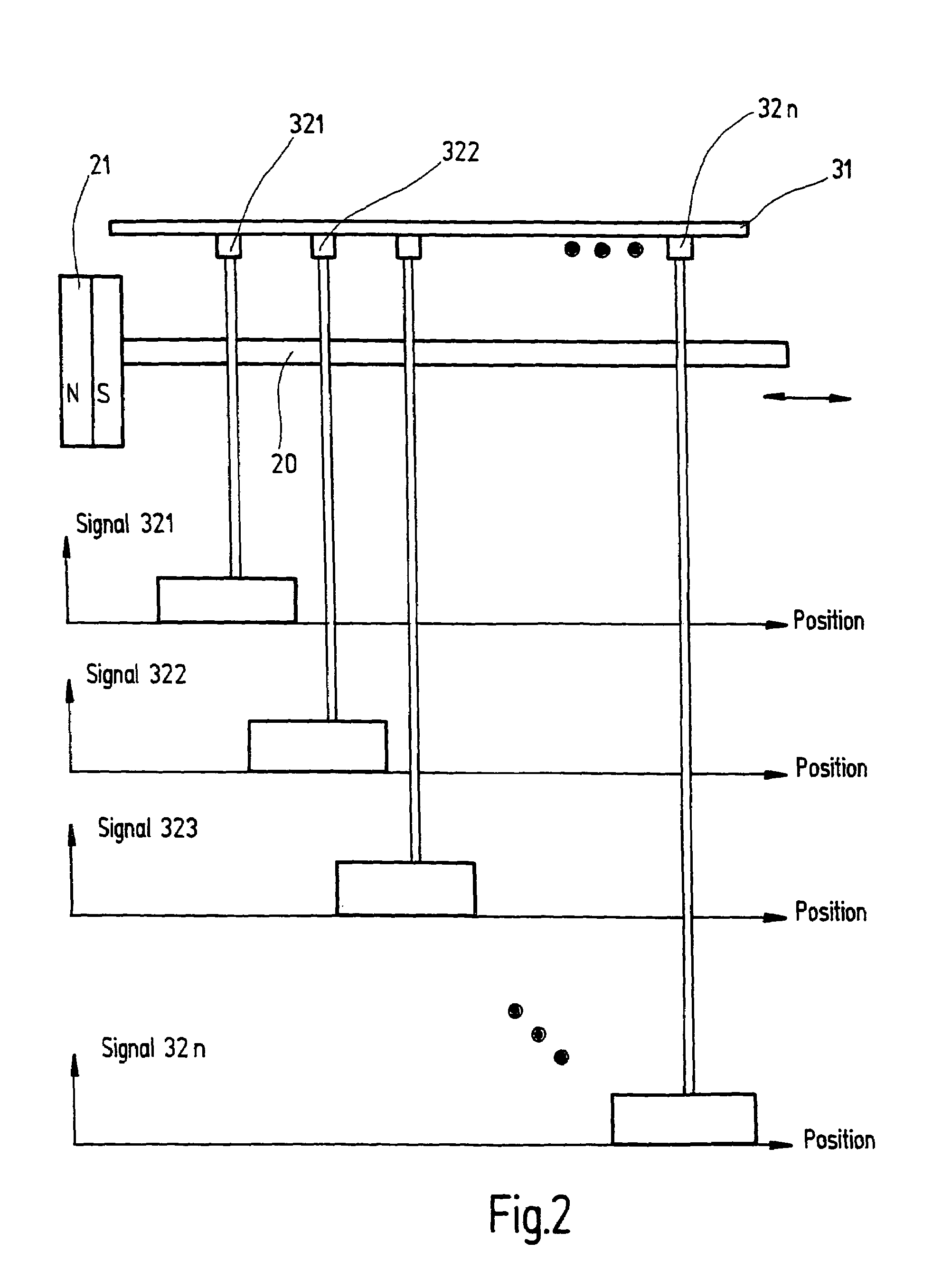
[0009]By arranging a Hall sensor array comprising at least two Hall sensors, spaced one from the other in the direction of movement of the piston, and one coil whose magnetic field permits the switching points of the Hall sensors to be adjusted in response to the current that can be applied to the coil, it is rendered possible in a very advantageous way to not only select individual Hall sensors electronically, but also and especially to allow interpolation between the different Hall sensors. It is thus possible to keep the number of Hall sensors small while simultaneously guaranteeing very high position-sensing precision.
[0010]The Hall sensor array advantageously comprises a plurality of equally spaced Hall sensors preferably arranged on a common substrate. This arrangement improves the position-measuring accuracy. In addition, adjusting the system to the required switching position can be effected by suitably selecting, electronically, the respective Hall sensors in a manner that will be described hereafter in more detail.
[0011]Preferably, the Hall sensors are arranged linearly one behind the other and are surrounded by a frame-like coil of substantially rectangular shape (frame-type coil). With an electric current flowing through the frame-type coil, the coil produces a magnetic field which superposes on the magnetic field of the magnetic region of the cylinder and which works especially well with the Hall sensors. This provides the advantageous possibility to vary the magnetic flux density at the point of installation of the Hall sensors, as a function of the coil current, and to thereby achieve sort of an interpolation effect for the response behaviour between the different Hall sensors.
[0012]According to an especially favorable embodiment, the frame-type coil is arranged on one side of the substrate, whereas the Hall sensors are arranged on the other side thereof. This arrangement leads to a very compact structure of the Hall sensor array.
[0017]A very essential advantage of this position-measuring device is seen in the fact that it can be adjusted electronically. Especially, no mechanical manipulations are required. Further, it is a considerable advantage that this position-measuring device, while its structure can be easily realized, allows the position of the piston of the cylinder-and-piston arrangement to be determined very precisely.

Problems solved by technology

Apart from the necessity to effect the adjustment manually, a further disadvantage of an arrangement of this kind is seen in the fissured surface of the cylinder, resulting from the particular structure, which practically excludes the use of such an arrangement in areas where higher demands are placed on hygiene, for example in the foodstuff or pharmaceutical industries.

Method used


Image

  • Position-measuring device for fluidic cylinder-and-piston arrangements
  • Position-measuring device for fluidic cylinder-and-piston arrangements
  • Position-measuring device for fluidic cylinder-and-piston arrangements

Examples


Embodiment Construction

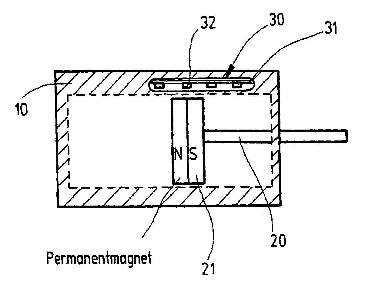
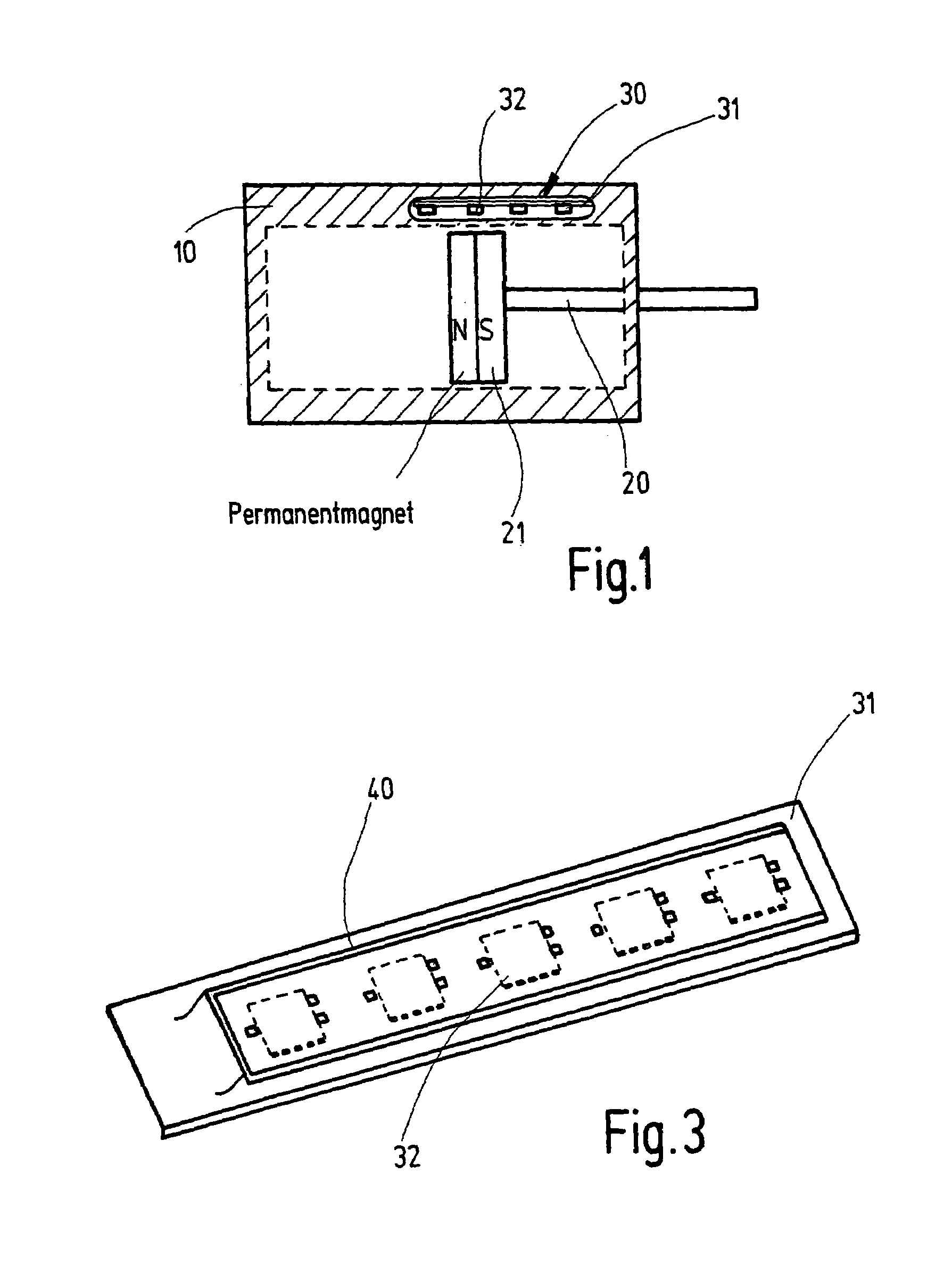
[0025]A cylinder-and-piston arrangement comprising a cylinder 10 and a piston 20 is represented diagrammatically in FIG. 1. A Hall sensor array, indicated by reference numeral 30, which comprises a plurality of Hall sensors 32 arranged on a circuit board 31, is provided in a wall of the cylinder. In the case of the cylinder-and-piston arrangement represented in FIG. 1, the Hall sensor array 30 is arranged in a cylinder wall. It is, however, understood that the invention is not limited to that arrangement, but that instead the Hall sensor array may also be arranged outside the cylinder wall or at a spacing from the latter, for example.

[0026]The Hall sensors 32 are positioned on the circuit board 31 linearly one behind the other and at substantially equal spacings one from the other along the direction of movement of the cylinder 20. The cylinder head 20 comprises a magnetic region, for example in the form of a permanent magnet 21. The Hall sensors 32 may be configured, especially, as...


PUM


Abstract

A position-measuring device for fluidic cylinder-and-piston arrangements having at least one Hall sensor, preferably arranged in the area of the cylinder wall, especially in a cylinder wall, and a magnetic region, arranged in the piston. At least one Hall sensor array has at least two Hall sensors spaced one from the other in the direction of movement of the piston. One coil is provided whose magnetic field permits the switching points of the Hall sensors to be adjusted in response to the coil current.

Description

BACKGROUND OF THE INVENTION[0001]The present invention relates to a position-measuring device or sensor for cylinder-and-piston arrangements.[0002]A position sensor of this kind, intended to indicate the position of a piston in the cylinder of a cylinder-and-piston arrangement in a braking system has been known, for example, from DE 100 53 995 A1. In the described arrangement, a hydraulic sensor cylinder is provided with a Hall element, the Hall sensor being inserted in the cylinder wall and a magnetic region being arranged in the cylinder-and-piston arrangement so that the movement of the piston in the cylinder will cause the Hall element to respond. A cylinder-and-piston arrangement wherein the position of the piston is sensed by means of Hall sensors has likewise been known From EP 0 536 926 B1.[0003]A position-measuring device for fluidic cylinders comprising a long measuring coil, designed as an eddy-current long-distance sensor, has been disclosed in DE 202 05 822 U1.[0004]It ...

Claims


Application Information

Patent Timeline
IPC IPC(8): G01B7/14G01B7/30F15B15/28G01D3/02G01D5/14
CPCG01D3/021F15B15/2861G01R33/0094G01D5/145
Inventor SIELEMANN, ULRICH
Owner NORGREN GMBH
Learn More