
Pod propulsion system with rim-mounted bearings

a propulsion system and rim-mounted technology, applied in the field of marine propulsion systems, can solve the problems of significant maintenance and reliability problems of the propulsion pod described above, performance degradation, and outright failure of the shaft bearing system

Active Publication Date: 2007-07-03
HUNTINGTON INGALLS
View PDF11 Cites 20 Cited by
  • Summary
  • Abstract
  • Description
  • Claims
  • Application Information

AI Technical Summary

Benefits of technology

"The present invention provides a new type of pod propulsion system that uses a rim-mounted bearing system instead of a hub mounted system with a shaft and fixed supports to mount the rotor(s). This new system has several advantages over traditional systems. Firstly, it allows for easier assembly and maintenance of the system. Secondly, it reduces the likelihood of damage to the rotor during operation. Thirdly, it improves the stability and efficiency of the system. Overall, this new system is more reliable, durable, and efficient than traditional systems."

Problems solved by technology

Historically, the propulsion pods described above have encountered significant maintenance and reliability problems including performance degradation and outright failure of the shaft bearing system.
Some of these problems are due, at least in part, to the difficulty in maintaining the correct hydrodynamic balance between the shaft, the pod housing / duct and the rotor as flow conditions and rotation speed change.
The typical shaft-based pod configuration also results in inherent problems in routing and maintaining lubrication to the shaft bearing system.

Method used


Image

  • Pod propulsion system with rim-mounted bearings
  • Pod propulsion system with rim-mounted bearings
  • Pod propulsion system with rim-mounted bearings

Examples


Embodiment Construction

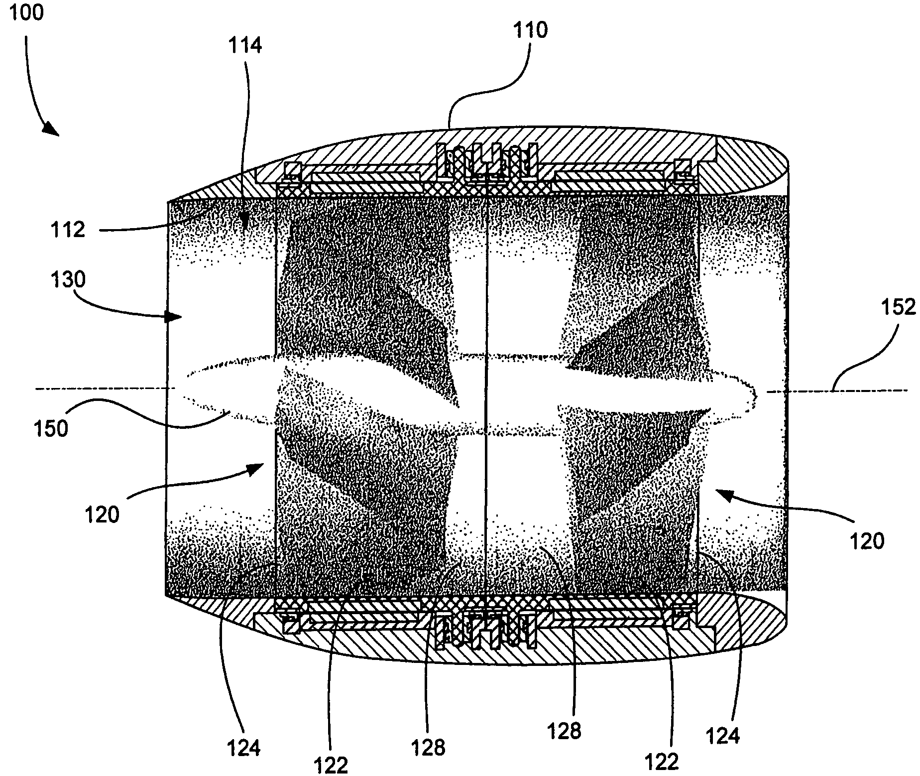
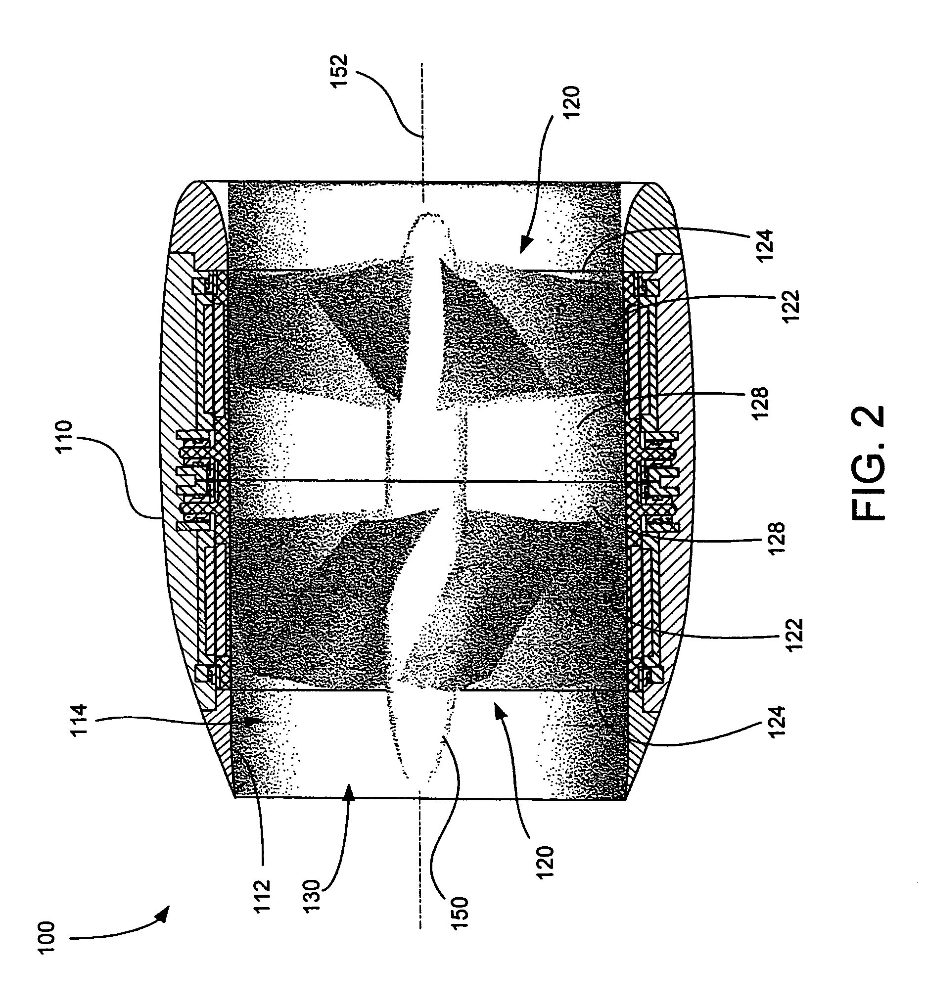
[0026]The present invention provides pod propulsion systems that use a rim-mounted bearing system rather than a shaft and fixed supports to mount the rotor(s). As used herein, the term rim-mounted refers to the fact that the bearings are mounted to a fixed structure outside the periphery of the rotating elements of the propulsion system. FIGS. 2 and 3 illustrate an exemplary pod propulsion system 100 using rim-mounted bearings according to an embodiment of the invention. The pod propulsion system 100 has a shroud or housing 110 having an inner wall 112 defining an interior space 114. The system 100 also has a pair of rotor units 120 disposed within the interior space 114, each comprising a rotor 122 attached within the interior of a rotating drum 124. It will be understood that while the exemplary embodiment has two rotor units 120, pod propulsion systems according to the invention may have only a single rotor unit or may have more than two rotor units 120. The rotors 122 may be att...


PUM


Abstract

A pod propulsion system comprises a housing defining a fluid duct and an annular drum rotatably mounted to the housing within the fluid duct. The annular drum has a drum interior and a cylindrical outer surface. The system further comprises a rotor mounted to the drum for rotation therewith, the rotor and the drum having a common axis of rotation. A bearing assembly mounted to the housing comprises a first bearing comprising a first plurality of bearing pads disposed circumferentially around the drum. Each pad has a pad bearing surface adapted to contact a first drum portion in a predetermined manner and is pivotably mounted to the housing so as to maintain contact of the pad bearing surface with the first drum portion in the predetermined manner when an orientation of the drum portion relative to the housing changes.

Description

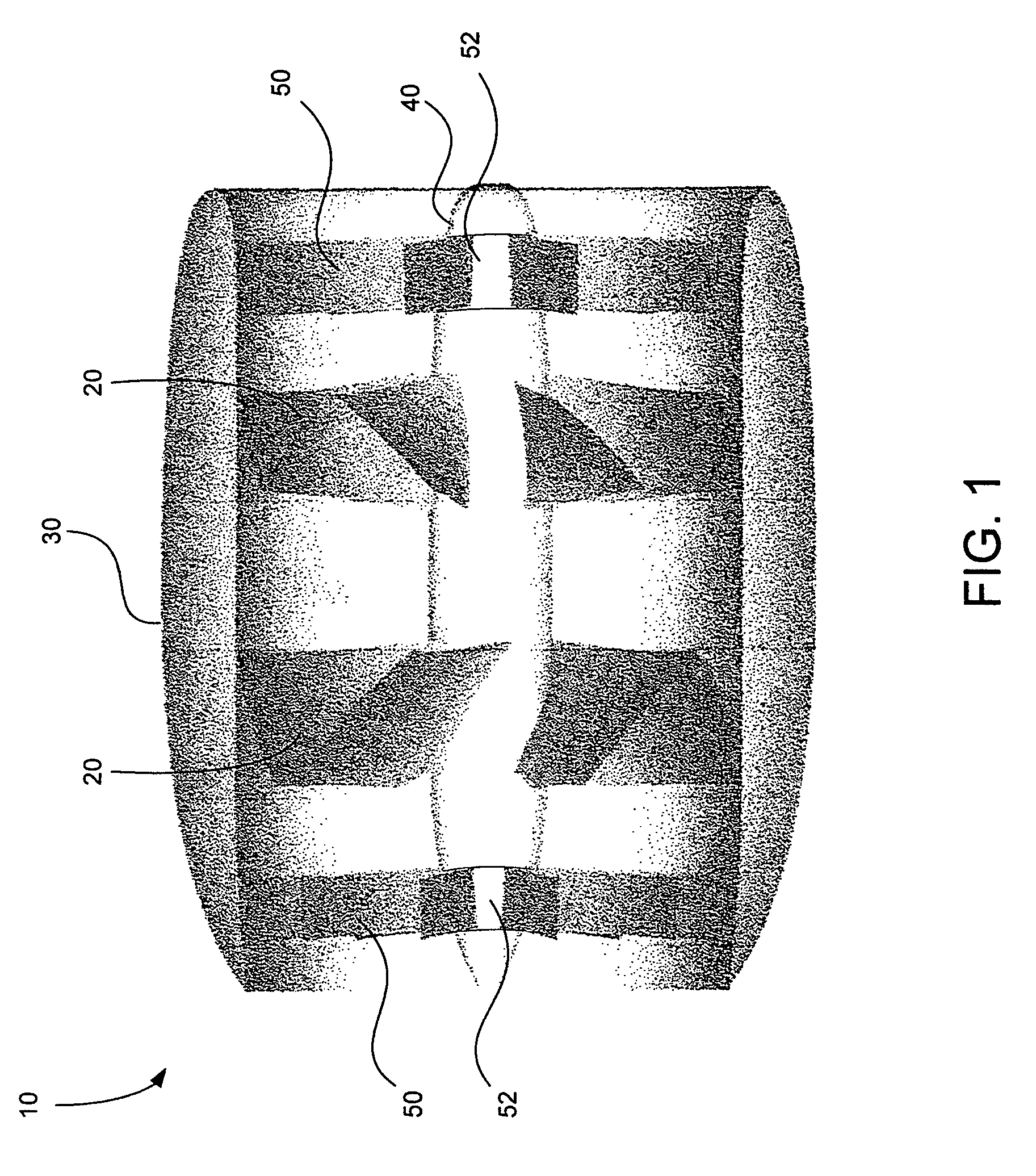
BACKGROUND OF THE INVENTION[0001]The present invention relates generally to maritime propulsion systems and, more particularly, to pod propulsion systems and bearing arrangements therefor.[0002]In recent years, pod propulsion systems have gained widespread use in large vessels such as cruise ships, ferries and cargo ships. These systems can generally provide high efficiency and maneuverability with lower noise generation than traditional shaft-driven rotor systems. They also provide a high degree of layout flexibility because of the relative independence of their location relative to the primary power plant of the vessel.[0003]Propulsion pods are relatively self-contained units that can be suspended beneath a ship's hull and independently azimuthly rotated. As shown in FIG. 1, a typical propulsion pod 10 includes one or more rotors 20 arranged within a duct or shroud 30. The rotors 20 are rotatably mounted to a shaft 40 that is centered within the duct 30 by one or more fixed suppor...

Claims


Application Information

Patent Timeline
Patent Type & Authority Patents(United States)
IPC IPC(8): B63H11/00
CPCB63H5/14B63H21/17F03B11/063F16C17/03F16C17/06F16C23/04F16C32/0651F16C32/0666B63H1/16B63H5/10B63H2005/1254B63H2005/1258B63H2023/005F16C2300/14Y02E10/226F16C2326/30Y02E10/20
Inventor TAYLOR, DOUGLAS LEEGOODING, DAVID ALBERTCOONS, SEAN ALLEN
Owner HUNTINGTON INGALLS
Learn More