
Child safety blind

a child safety and blind technology, applied in the field of window blinds, can solve the problems of posing a possible safety hazard to small children, prior art cleats are prone to be unreliable in preventing cord deaths, etc., and achieve the effect of effectively preventing accidental strangulation

Inactive Publication Date: 2007-06-05
3 DAY BLINDS
View PDF2 Cites 59 Cited by
  • Summary
  • Abstract
  • Description
  • Claims
  • Application Information

AI Technical Summary

Benefits of technology

[0014]The present invention further provides a method of retrofitting conventional prior art blinds to become a child safety blind. In the retrofitting method, the lift cord or cords of the prior art blind is cut and removed from the blind. Before the cutting step, the blind is preferably lowered to a fully extended, i.e. closed, position. After the lift cord is removed from the blind, the slats are solely supported by the ladder tapes. To raise the blind to an open position, a pair of registry clips is preferably used to receive and register the bottom rail and the slats therein, and to manually raise the bottom rail and the slats towards the head rail. To avoid the slats sliding out laterally, the pair of the registry clips are used simultaneously and preferably maintained at the same horizontal level during the raising process. The slats and the bottom rail may then be maintained in an open position by releasing the registry clips to engage the head rail or valence of the blind. Further, to subsequently release the slats to a closed or extended position, the registry clips are disengaged from the head rail and gradually lowered until the blind is fully extended. Again, the pair of the registry clips, plus the gradual lowering process, prevents the slats from laterally sliding out of the support ladder tapes.
[0015]As the child safety blind provided by the present invention does not include a lift cord, accidental strangulation is effectively prevented.

Problems solved by technology

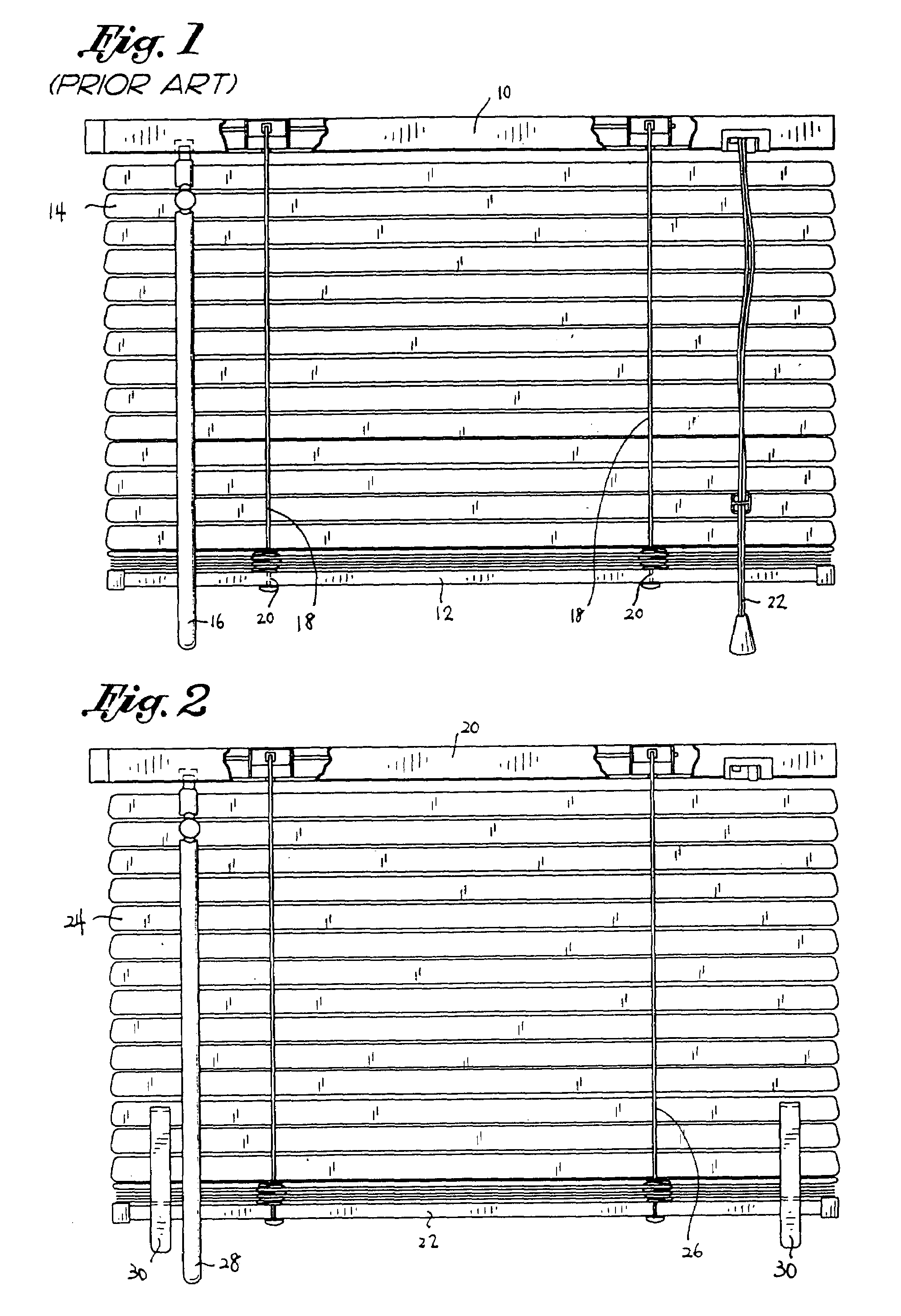
However, when the blind is partly raised as shown in FIG. 1, or raised to a fully open position, the lift cords 22 extend downwardly and become readily accessible to small children, thereby posing a possible safety hazard to small children.
Recently, various accidental cord deaths to small children have been reported which has caused manufacturers to investigate and attempt to provide increased child safety devices.
However, most of the cleats require special tools or procedures, including drilling and screwing to mount the same as well as require the user to always manually wind the cord about the cleat.
As such, the prior art cleats are prone to be unreliable in preventing cord deaths.

Method used


Image

  • Child safety blind
  • Child safety blind
  • Child safety blind

Examples


Embodiment Construction

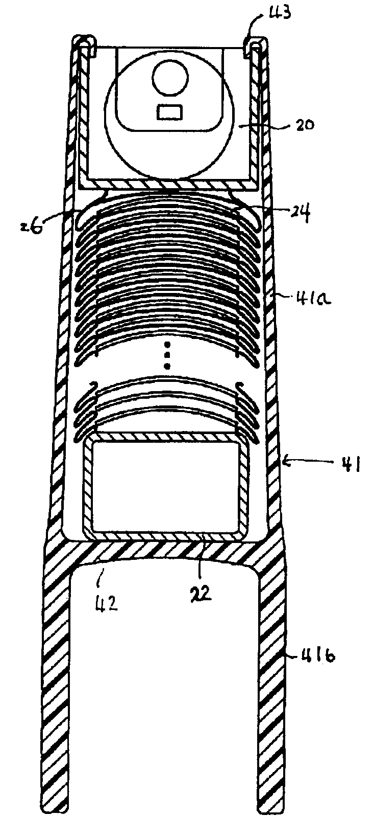
[0028]The present invention provides a child safety blind which can be raised to a fully open position or lowered to an extended or closed position without using the lift cord used in a conventional blind. The child safety blind is applicable to all types of horizontal blinds such as wood blinds, faux wood blinds, bamboo blinds, mini blinds, metallic blinds, fabric cell blinds, and vinyl blinds and for purposes of this application, the term blind shall include all of the same. FIG. 2 depicts one embodiment of the child safety blind provided by the present invention. As shown in FIG. 2, the child safety blind comprises a head rail 20, a bottom rail 22, and a plurality of slats 24 horizontally extending between the head rail 20 and the bottom rail 22. The child safety blind further comprises a pair of ladder tapes 26. Each of the ladder tapes 26 comprises a plurality of steps or loops, and each slat 24 extends through a pair of corresponding steps of the ladder tapes 26. The blind als...


PUM


Abstract

A child safety blind having a head rail, a bottom rail, at least one ladder tape, a plurality of slats, a tilt wand and a pair of registry clips. At least one ladder tape extends horizontally between the head rail and the bottom rail, and the ladder tape comprising a plurality of steps. The slats extend horizontally between the head rail and the bottom rail, and each of the slats extends through one corresponding step of the ladder tape. The tilt wand is linked with ladder tape and operative to operative to drive the steps of the ladder tape to turn the slats with an angle. The pair of registry clips is operative to lift the bottom rail and the slats at two side portions thereof while holding the bottom rail and the slats therein.

Description

[0001]This application is a divisional application of and claims the benefit from U.S. application Ser. No. 10 / 394,607, which was filed Mar. 21, 2003 now U.S. Pat. No. 6,994,143.CROSS-REFERENCE TO RELATED APPLICATIONS[0002]NOT APPLICABLESTATEMENT RE: FEDERALLY SPONSORED RESEARCH / DEVELOPMENT[0003]NOT APPLICABLEBACKGROUND OF THE INVENTION[0004]The present invention relates in general to a window blind and, more particularly, to a child safety blind which can be raised or lowered without using a conventional lift or draw cord.[0005]Blinds have been widely used to prevent sunlight from entering an area and to retain privacy. Typically, blinds include a plurality of slats, vanes or fabric pleats hung horizontally from a head rail.[0006]FIG. 1 shows a conventional prior art horizontal blind. The blind comprises a head rail 10, a bottom rail 12, a plurality of slats 14 disposed between the head rail 10 and the bottom rail 12, a tilt rod or tilt wand 16, a pair of ladder tapes 18 driven by ...

Claims


Application Information

Patent Timeline
Patent Type & Authority Patents(United States)
IPC IPC(8): E06B9/30E06B9/32
CPCE06B9/32Y10T24/44855Y10T24/44872
Inventor MCCARTY, MICHAEL J.GUTIERREZ, FRANK A.
Owner 3 DAY BLINDS
Learn More