
Urethral occlusive assembly for preventing urinary incontinence

a technology of urethral occlusive and assembly, which is applied in the field of urethral occlusive assembly, can solve the problems of increased urine leakage, prone to component failure, and complex device to implant, and achieve the effect of improving the urethral occlusive assembly

Inactive Publication Date: 2007-05-29
GT UROLOGICAL
View PDF21 Cites 32 Cited by
  • Summary
  • Abstract
  • Description
  • Claims
  • Application Information

AI Technical Summary

Benefits of technology

The solution provides effective and adjustable urinary continence with reduced risk of tissue damage and discomfort, allowing for easy removal and reapplication of the external magnet for voiding, eliminating the need for complex implanted component operation and minimizing surgical complications.

Problems solved by technology

The AUS 800 is a complicated device to implant.
The requirement of multiple components and the required intraoperative techniques make it prone to component failure.
Some common failures include infection, urethral erosion and atrophy leading to increased urine leakage.
Additionally, fluid leaks due to tubing disconnection, intraoperative punctures, and silicone wear within the silicone urethral cuff folds are also causes of device failure.
For the clamp to be effective, however, imparts large clamping forces on the penis that often lead to pain, swelling and penile skin break down.
As there is great penile anatomical variation requiring multiple clamp sizes, it may be frequent that an improper clamp is selected.
Further, the ability to operate the strapping system is often difficult for older, arthritic men.
Such inconsistencies in sizing and the user dependent strapping system, however, make the C3 less reliable in its ability to control leakage.
Difficulties with the MEC include skin sensitivity to materials, tissue sloughing due to the constantly wet environment, manual dexterity required for application, leakage due to adhesive release, and change in penis size during wearing time and penile retraction.
Some synthetic bulking agents, may not be resorbed, but are prone to migrate and reduce coaptation of the urethra.
However, the performance of injectables in men has not met expectations, and is not widely used.

Method used


Image

  • Urethral occlusive assembly for preventing urinary incontinence
  • Urethral occlusive assembly for preventing urinary incontinence
  • Urethral occlusive assembly for preventing urinary incontinence

Examples


Embodiment Construction

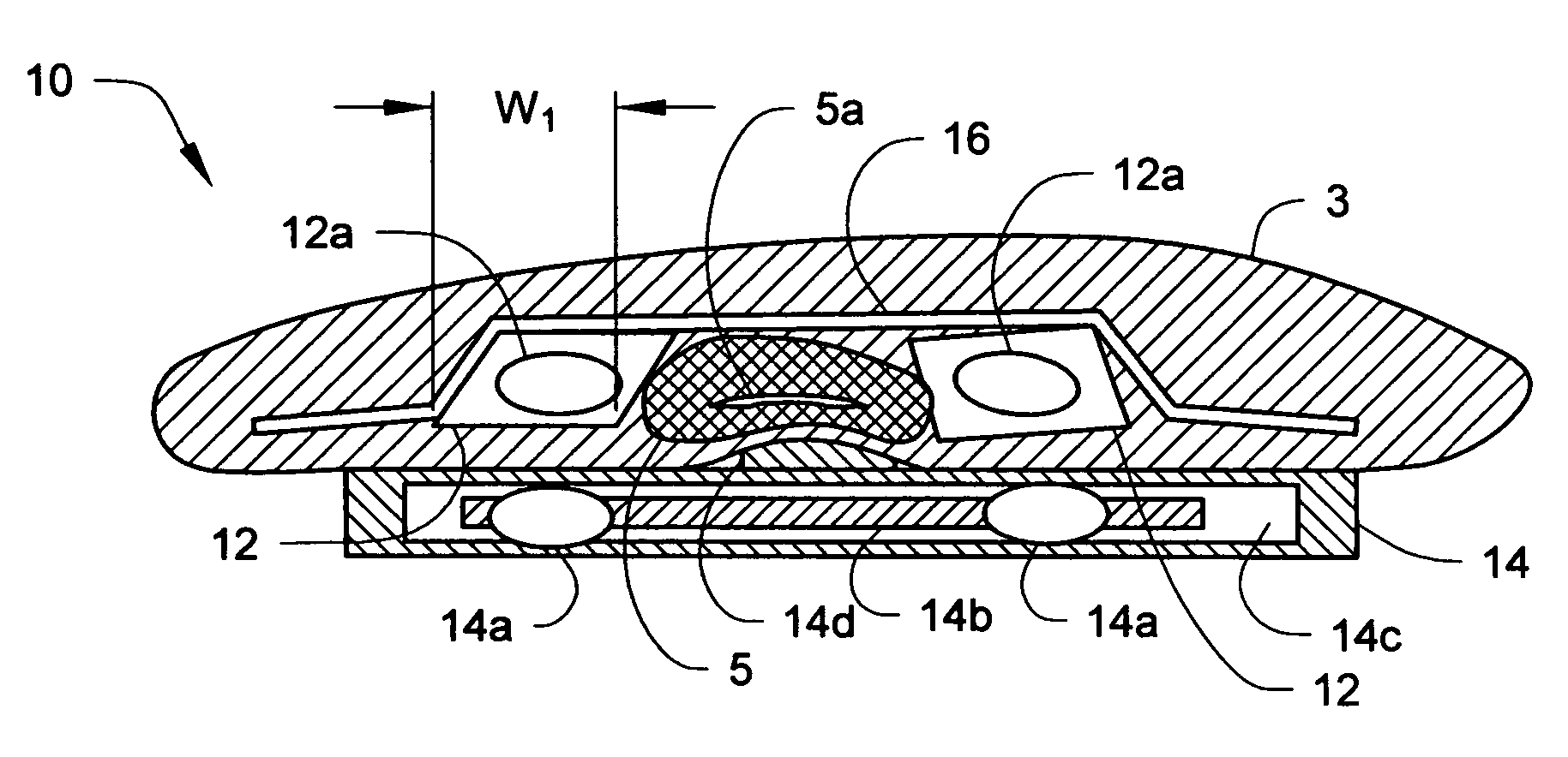
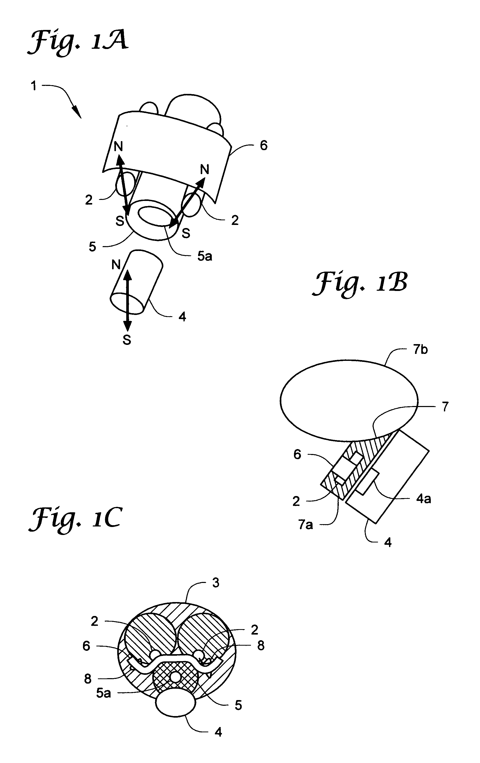
[0077]One embodiment of a urethral occlusive assembly 1 is provided in FIGS. 1A–3B. FIGS. 1A and 1C illustrate the urethral occlusive assembly 1 as applied to a male urethra 5, and FIG. 1B shows an embodiment of the urethral occlusive assembly 1 vaginally applied to a female urethra 7.

[0078]The urethral occlusive assembly 1 provides an implant component including implant magnets 2 connected with a flexible bridge member 6. The implant component is implanted inside a patient's body and around a male 5 or female urethra 7. Preferably, the implant magnets 2 and bridge member 6 are arranged on a dorsal surface of the male 5 or female urethra 7, such that the implant magnets 2 straddle either urethra.

[0079]The implant component may be secured to surrounding tissue, such as penile tissue of a male urethra 5 (FIG. 1C). In one embodiment, suture attachments 8 preferably fix the flexible bridge member 6 to surrounding penile tissue of the urethra 5.

[0080]Preferably, the implant component pro...


PUM


Abstract

A urethral occlusive assembly includes an implant component and external component. The implant component includes a flexible bridge member connecting two opposed implant supports. The implant component is implanted about a dorsal surface of an animal urethra. An external component is disposed external to and proximate the animal urethra. The external component operatively communicates with the implant component to transmit a compressive load on the urethra. By communication between the implant and external components, either the implant component or the external component actively compresses the urethra against the flexible bridge member, thereby effecting urinary continence.

Description

CROSS-REFERENCE TO RELATED APPLICATIONS[0001]The present application draws priority from U.S. Provisional Patent Application Ser. Nos. 60 / 569,420 and 60 / 600,613, both entitled “Magnetic Urethral Occlusive Device,” and both of which are incorporated herewith by reference in their entirety.[0002]This invention was made with government support under SBIR Grant Number 1R43DK066941-01A2 awarded by the National Institutes of Health. The government has certain rights in the invention.FIELD OF THE INVENTION[0003]The invention relates to a urethral occlusive device for preventing urinary incontinence. More particularly, the invention relates to a urethral occlusive assembly and method for the same employing an implant component operatively communicating with an external component, whereby one of the implant or external components actively compresses a patient's urethra to prevent urinary incontinence.BACKGROUND OF THE INVENTION[0004]Urethral occluding devices are well known and widely used t...

Claims


Application Information

Patent Timeline
Patent Type & Authority Patents(United States)
IPC IPC(8): A61F2/02A61F2/00A61F2/04
CPCA61F2/0036A61F2/0054
Inventor TIMM, GERALD W.ANDERSON, DAVID W.
Owner GT UROLOGICAL
Learn More