
Instrument case stand

a technology for instruments and stands, applied in the direction of instruments, machine supports, music aids, etc., can solve the problems of instruments being exposed to damage, musicians are commonly faced with challenges, and musical instruments may be expensive and damaged

Inactive Publication Date: 2007-04-24
BURCH CHAD +1
View PDF52 Cites 31 Cited by
  • Summary
  • Abstract
  • Description
  • Claims
  • Application Information

AI Technical Summary

Benefits of technology

"The present disclosure relates to a stand device that can be attached to an instrument case for supporting musical instruments in an upright position. The stand device is designed to securely store the instrument case and protect the instrument from damage when not in use. The stand device is easy to use, compact, and aesthetically pleasing. The technical effects of the stand device include providing a convenient and safe way to store and protect musical instruments, reducing the risk of damage or damage to the instrument case, and providing a stand device that is easy to transport and manipulate."

Problems solved by technology

Musicians are commonly faced with the challenge of finding a place to safely store their musical instruments.
Such musical instruments may be expensive and may be damaged if not properly protected.
This is an undesirable method of storing the instruments since the musical instrument may slip from its stored position causing damage to either the instrument, the wall, or the furniture on which the instrument is supported.
Sometimes the stands are configured to attach directly to the musical instrument which may leave the instrument exposed for damage and require additional space to store the instrument case.
Storing a musical instrument out of its case causes the instrument to be more vulnerable to damage from dust, or accidental damage from children or pets for example.
Other instrument stands may be bulky and difficult to transport, store, or manipulate, or the instrument stands may be unsightly in appearance.

Method used


Image

  • Instrument case stand
  • Instrument case stand
  • Instrument case stand

Examples


Embodiment Construction

[0027]For the purposes of promoting an understanding of the principles in accordance with the disclosure, reference will now be made to the embodiments illustrated in the drawings and specific language will be used to describe the same. It will nevertheless be understood that no limitation of the scope of the disclosure is thereby intended. Any alterations and further modifications of the inventive features illustrated herein, and any additional applications of the principles of the disclosure as illustrated herein, which would normally occur to one skilled in the relevant art and having possession of this disclosure, are to be considered within the scope of the invention claimed.

[0028]It must be noted that, as used in this specification and the appended claims, the singular forms “a,”“an,” and “the” include plural referents unless the context clearly dictates otherwise. Moreover, as used herein, the terms “comprising,”“including,”“containing,”“characterized by,” and grammatical equ...


PUM


Abstract

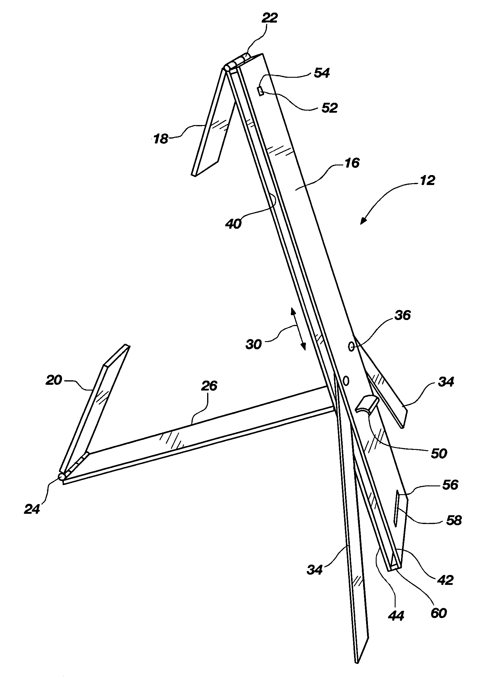
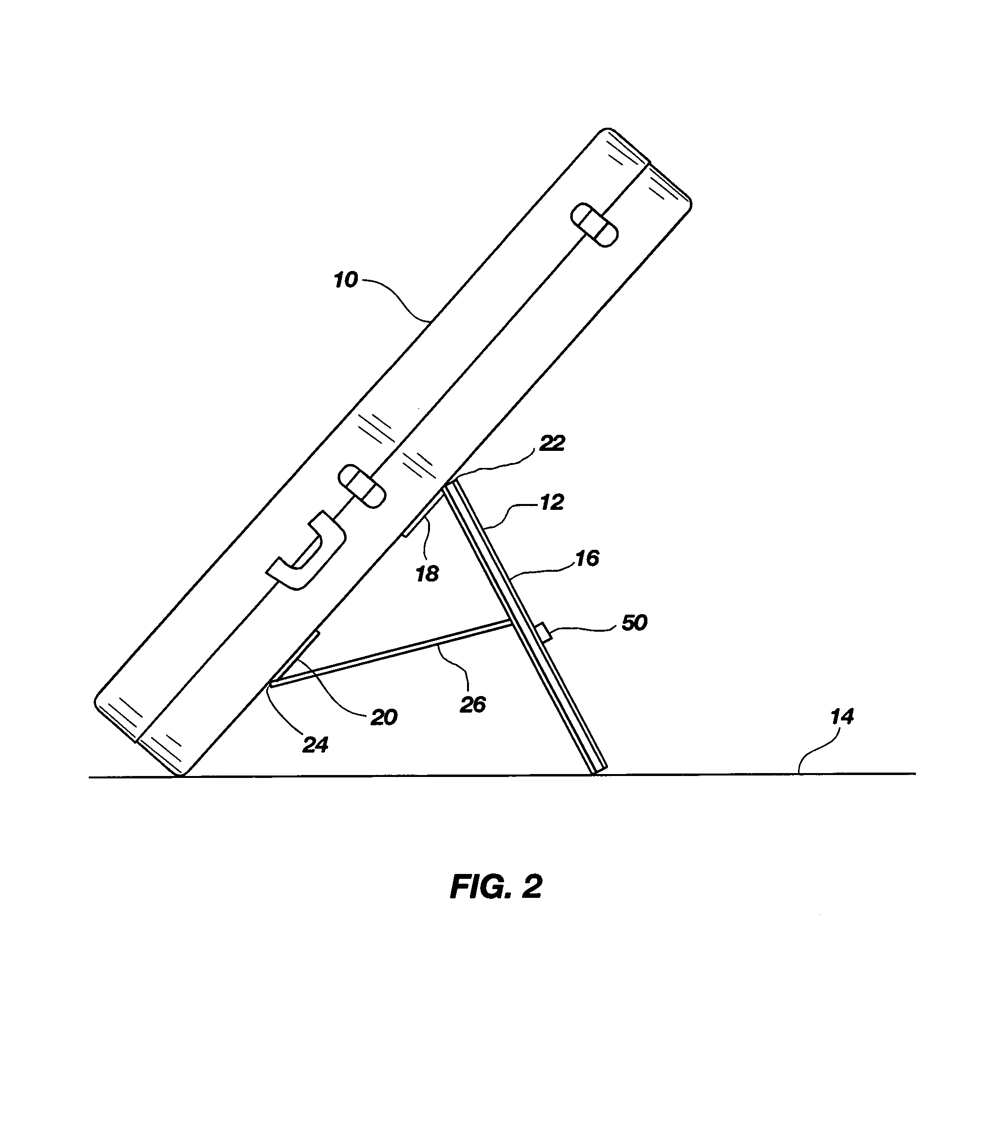
A stand device for use with objects such as musical instrument cases. The stand can be attached to an instrument case for supporting the instrument case in an upright position. The musical instrument may be stored within the case for protection against the elements or accidental damage. The stand may be placed in an extended position for supporting the musical instrument case, or the stand may be retracted to a compact configuration to facilitate transporting, storing and handling the stand. The stand may include a body that may be attachable to the instrument case through a pair of connectors and a brace member. The body may also have a pair of legs for providing additional stability to the stand. When the stand is retracted, the connectors, brace member and legs may be received within the body so as to be out of view.

Description

CROSS-REFERENCE TO RELATED APPLICATIONS[0001]This application claims the benefit of U.S. Provisional Application No. 60 / 518,961, filed Nov. 10, 2003, which is hereby incorporated by reference herein in its entirety, including but not limited to those portions that specifically appear hereinafter, the incorporation by reference being made with the following exception: In the event that any portion of the above-referenced provisional application is inconsistent with this application, this application supercedes said above-referenced provisional application.STATEMENT REGARDING FEDERALLY SPONSORED RESEARCH OR DEVELOPMENT[0002]Not Applicable.BACKGROUND[0003]1. The Field of the Invention[0004]The present disclosure relates generally to support devices, and more particularly, but not necessarily entirely, to stand devices that can be attached to objects such as instrument cases to support instruments in an upright position.[0005]2. Description of Related Art[0006]Musicians are commonly fac...

Claims


Application Information

Patent Timeline
Patent Type & Authority Patents(United States)
IPC IPC(8): G10G5/00G10D3/00G10G1/00G10G7/00
CPCG10G5/00G10G7/005
Inventor BURCH, CHADBURCH, JR., CHARLES E.GUEST, JOHN
Owner BURCH CHAD
Learn More