
Folding bunk bed

a bunk bed and folding technology, applied in the field of folding bunk beds, can solve the problems of reducing the operation of cable-actuated folding bunk beds, limiting the bed deck to twin beds,

Active Publication Date: 2007-04-24
R N R INT
View PDF2 Cites 24 Cited by
  • Summary
  • Abstract
  • Description
  • Claims
  • Application Information

AI Technical Summary

Benefits of technology

[0006]The various embodiments, both manually operated and power operated, of the folding bunk beds of this invention use a vertically shifting pivot point to accommodate larger bed decks. The bed decks are hinged to carriages that slide on vertically mounted shaft (a smooth rod for manually operated embodiments and a threaded screw shaft for power operated embodiments) within a wall frame. Bed decks are mounted to support arms that are pivotally connected to the carriages. A linkage mechanism or guide track allows the bed decks to pivot simultaneously between a horizontal sleep position and a vertical storage position as the carriages shift along the shafts. The vertically shifting pivot point allows the bed decks to kneel down, that is to fold up at a pivot point lower on the wall. The shifting pivot point not only accommodates larger bed decks and eliminates the problems associated with cable supports, but allows bed decks to overlap in the storage position.
[0007]Accordingly, the bunk beds of this invention have several advantages over conventional folding bunk beds. In particular, the bunk beds of this invention accommodate larger bed decks.
[0008]Another advantage is that the bed decks can be overlapped in the storage position, which allows a lower bed deck limited only by ceiling height.
[0009]Another advantage is that the screw shaft actuation mechanism is more reliable than cable actuated mechanisms and does not require complex mechanical adjustments.
[0010]Another advantage is that the actuation mechanism is enclosed entirely within the wall frame, which reduces unsightly cable and reduces possible safety hazards.
[0011]Another advantage is that the mattress and bedding can be stored on the bed decks when the bunk beds are in the vertical storage positions.

Problems solved by technology

In a recreational vehicle application, where ceiling heights are relatively low, bed decks typically are limited to twin bed sizes.
Cable slack, binding and unspooling are frequent problems that seriously detract from the operation of cable actuated folding bunk beds.

Method used


Image

  • Folding bunk bed
  • Folding bunk bed
  • Folding bunk bed

Examples


first embodiment

Bunk Bed

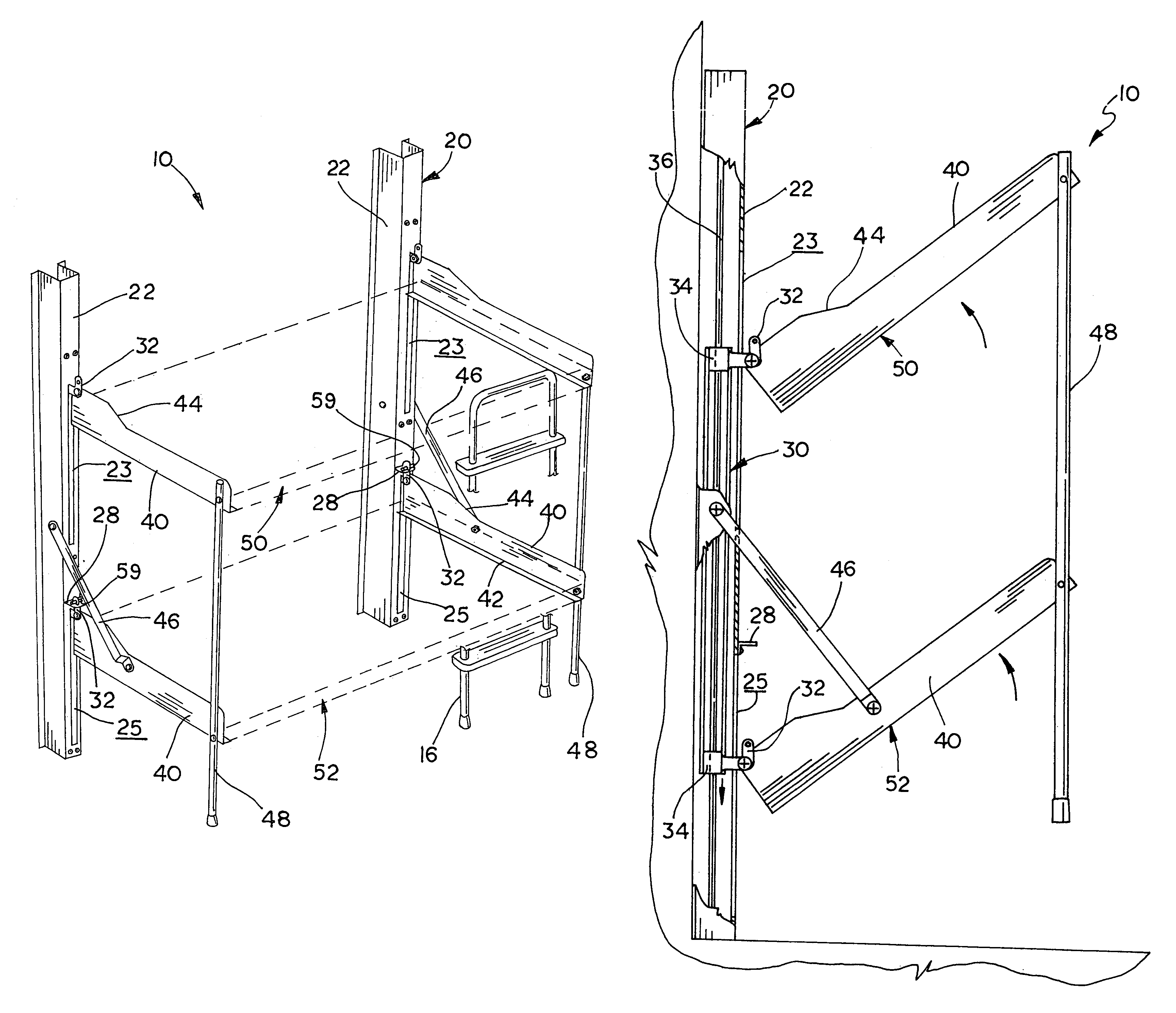
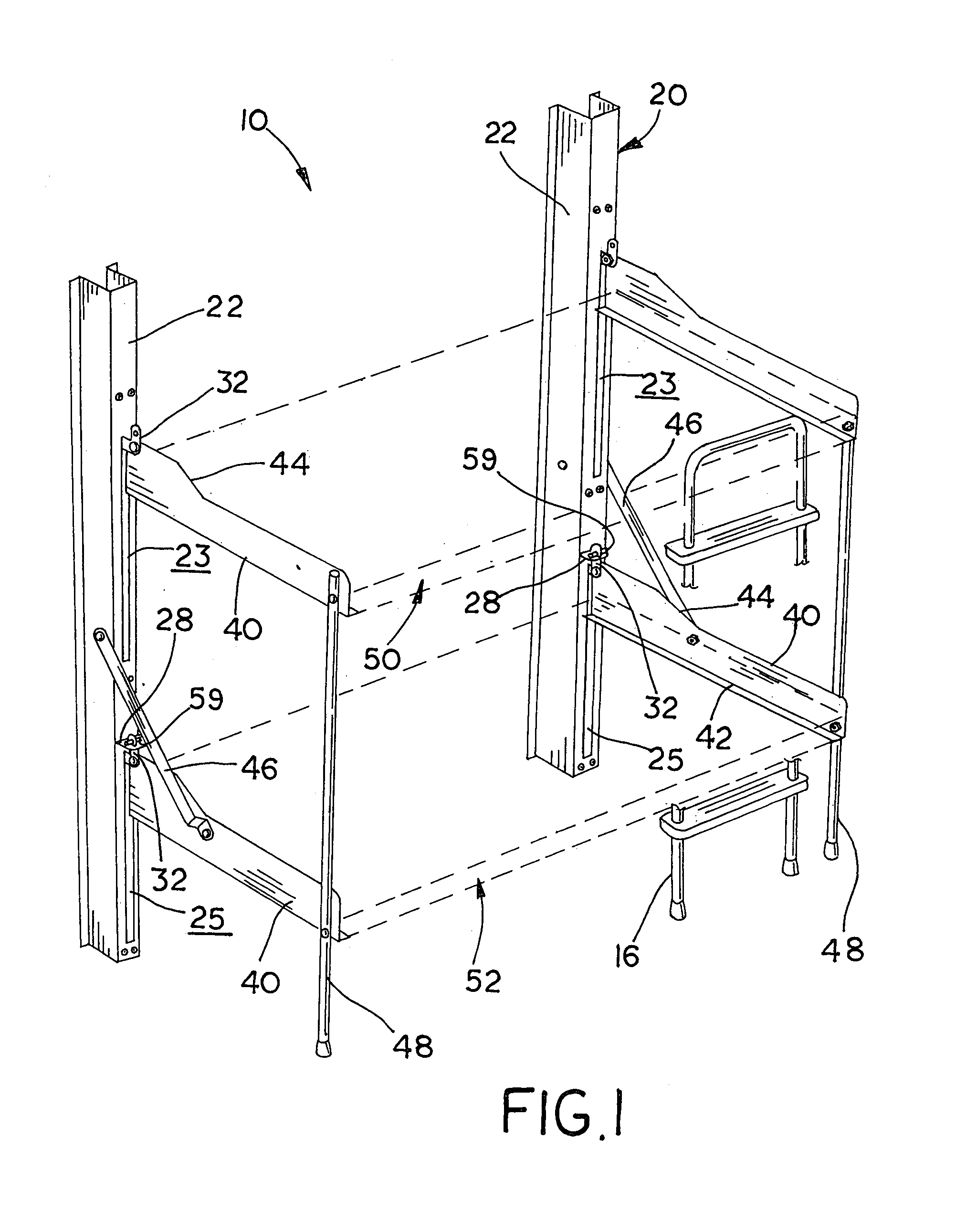
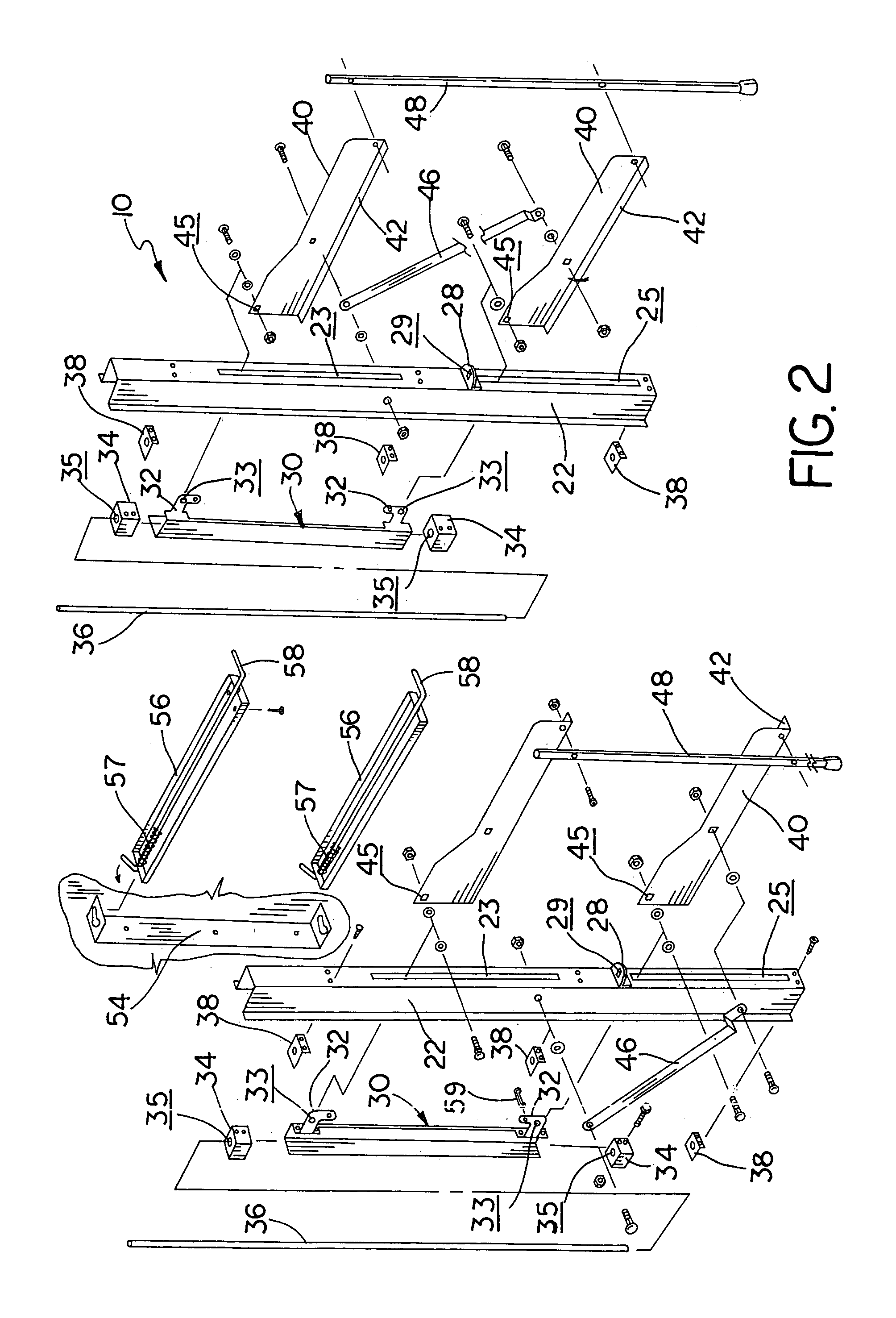
[0035]FIGS. 1–7 illustrate the first manually operated embodiment of the bunk bed of this invention, which is designated generally as reference numeral 10. Bunk bed 10 includes a wall frame 20, which is secured to a vertical wall, a pair of carriages 30 shiftably mounted on shafts 36 vertically disposed within the wall frame, and a pair of bed decks (upper deck 50 and lower deck 52) pivotally connected to the carriages.

[0036]Wall frame 20 secures bunk bed 10 to the interior walls of a structure or vehicle and provide the structural supports for the bunk bed. Wall frame 20 is mountable to an interior wall of a house or recreational vehicle (not shown) using screws, bolts, adhesive or other suitable methods well known in the arts. Wall frame 20 includes a pair of uprights 22, which are constructed of a section of metal U-channel. As shown, each upright 22 has two elongated longitudinal slots (upper 23 and lower 25). A long shaft 36 is vertically disposed within each upright 22...

second embodiment

erlapping Bunk Bed

[0040]FIGS. 8 and 9 illustrate a second embodiment of the manually folding bunk bed of this invention, which is designated generally as numeral 60. Bunk bed 60 is similar in construction and operation to bunk bed 10 above, except that the lower bed deck 62 is significantly larger and folds to overlie the upper bed deck 64. As shown, the lower deck support arm 66 has a greater depth, which spaces the deck further from the wall frame to allow the lower deck to overlie the upper deck. Bunk bed 60 also includes separate bed posts 68 to connect the bed decks and post feet 69 to support the decks.

third embodiment

nk Bed with Linkage

[0041]FIGS. 10–14 illustrate a third embodiment of the folding bunk bed assembly of this invention, which is designated generally as reference numeral 10. Bunk bed 70 is a powered version of the first embodiment of the folding bunk bed of this invention. Bunk bed 70 is substantially similar to bunk bed 10 in design, construction and operation, except that it includes a powered actuation mechanism supported and enclosed within the wall frame. The powered actuation mechanism eliminates the carriage so that the bed decks are hinged directly to bearing blocks that travel along a pair of screw shafts. Again, a linkage is connected between the support arms of one bed deck and the upright of the wall frame and bed posts are used to support the bed decks in the sleep position.

[0042]The actuation mechanism includes an electric motor 72, a coupler 73, two gear boxes 74, a drive axle 75, a pair of screw shafts 76 and two pairs of bearing blocks 78. Ideally, motor 72 is a con...


PUM


Abstract

The folding bunk beds of this invention fold between a horizontal sleep position and a vertical storage position. The various embodiments, both manually operated and power operated, of the folding bunk beds use vertically shifting pivot points to accommodate larger bed decks. The bed decks are hinged to carriages that slide on vertical shafts mounted within a wall frame. Bed decks are mounted to support arms that are pivotally connected to the carriages. A linkage mechanism or guide track allows the bed decks to pivot simultaneously between a horizontal sleep position and a vertical storage position as the carriages shift along the shafts. The vertically shifting pivot point allows the bed decks to kneel down, that is to fold up at a pivot point lower on the wall.

Description

[0001]This application claims priority based upon Provisional Application Ser. No. 60 / 554,946 filed Mar. 22, 2004 now abandoned.[0002]This invention relates to bunk beds and particularly folding bunk beds that pivot between a horizontal sleep position and a vertical storage position.BACKGROUND OF THE INVENTION[0003]Bunk beds are commonly used in applications where living space is limited, such as in small apartments and recreational vehicles. To further utilize living space in such applications, bunk beds often have sleeping decks that are hinged to the wall so that they can be pivoted into a storage position when not used. Folding bunk beds have been developed that are both manually and automatically operated. While popular for utilizing available living space, conventional manual and automatic folding bunk beds have several practical shortcomings.[0004]Heretofore, the bed decks are hinged to the wall or a wall mounted frame at a fixed point, which limits the size of the bed decks ...

Claims


Application Information

Patent Timeline
Patent Type & Authority Patents(United States)
IPC IPC(8): A47C17/00A47C17/38A47C17/50A47C19/20
CPCA47C17/50A47C19/20
Inventor GARDNER, STEWARD E.
Owner R N R INT
Learn More