Radio frequency identification RFID tag

a radio frequency identification and tag technology, applied in the field of rfid tags, can solve the problems of increased cost of rfid tags, difficult to meet the expectations of the market, and higher cost, so as to reduce the size of antennas, enhance radiation capability, and reduce the input impedance of antennas.

Inactive Publication Date: 2007-03-27
WHA YU IND CO LTD
View PDF13 Cites 6 Cited by
  • Summary
  • Abstract
  • Description
  • Claims
  • Application Information

AI Technical Summary

Benefits of technology

[0015]1. In the present invention, the area of conductor plane 201 is designed to be bigger than that of conductor pressing section 202, thus yielding an image effect for antenna. This can reduce significantly the size of antenna, but also enhance greatly the radiation capability to match the required frequency range. Also, thanks to the plane layout of conductor plane 201 that assists in reducing input impedance of antenna in a more efficient and easier way than conventional antenna (dipole antenna), while optimizing the impedance match of antenna 20. Therefore, it is possible to provide a miniaturized RFID TAG, and reduce the production and test cost of antenna for a higher economical efficiency.
[0016]2. Based on the special embedding structure of wireless telecommunication IC 30, the present invention can offer a thin-profile wireless telecommunication IC 30 with much simplified manufacturing process. Also, thanks to the structure of two lead frames 3132 fitted with convex linear pins 311321, electrical connection between wireless telecommunication IC 30 and antenna 20 can be achieved by means of welding. For RFID tags with insufficient mass production, the assembly and manufacturing process of wireless telecommunication IC 30 and antenna are simpler and flexible. Therefore, no high-duty manufacturing process and equipments shall be required for this purpose, thereby helping to minimize the manufacturing cost of RFID tags and promote the overall economical efficiency.

Problems solved by technology

The price of RFID TAG includes manufacturing cost of IC chip, antenna and package.
The size of antenna for UHF RFID tag is still a little bigger, thus leading to an increased cost of RFID tag, and making it difficult to meet the expectation of market due to failure of miniature.
In addition to a higher cost, the oversize of RFID TAG will make it difficult to be adhered to a smaller product.
However, this manufacturing process requires specific instruments and high-duty manufacturing modules for cost effectiveness.
So, a small amount of diversified RFID tags will generate disadvantages such as difficult manufacturing process and increasing cost.

Method used


Image

  • Radio frequency identification RFID tag
  • Radio frequency identification RFID tag
  • Radio frequency identification RFID tag

Examples


Embodiment Construction

[0025]The features and the advantages of the present invention will be more readily understood upon a thoughtful deliberation of the following detailed description of a preferred embodiment of the present invention with reference to the accompanying drawings.

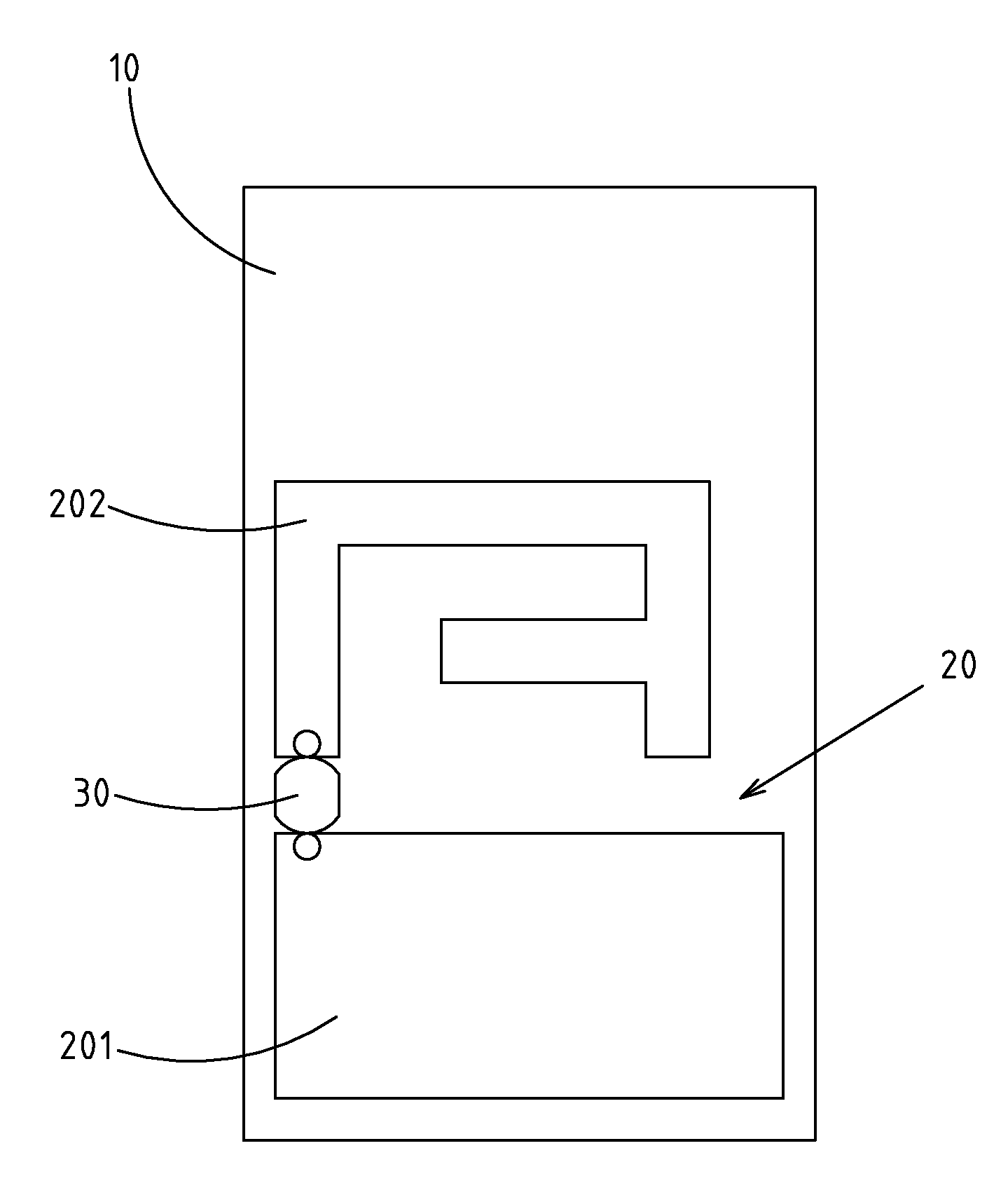
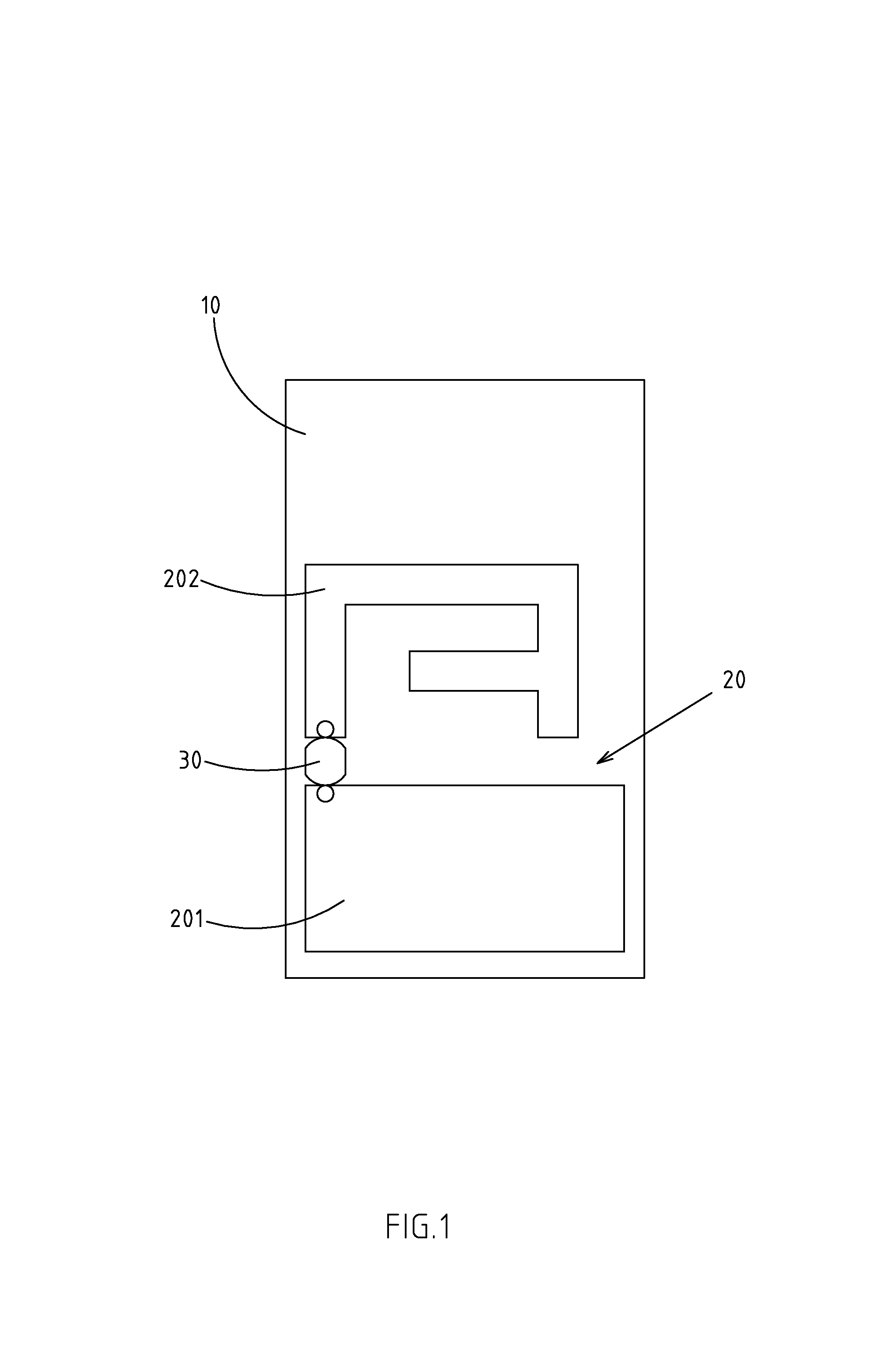
[0026]As shown in FIG. 1, there is a RFID tag embodied in the present invention.

[0027]The invention includes a substrate 10, which is constructed of flexible materials, such as Polyimide or polyester organic materials, or inflexible ones, such as porcelain, glass and PCB, or resin for processing of PCB, typically as epoxy resin;

[0028]There is also an antenna 20m which is adhered to the surface of substrate 10, which is constructed of conducting materials, such as Cu-or Al-inclusive metallic conductor or microwave carbon fiber material. The antenna 20 is provided with a conductor plane 201 and a conductor pressing section 202, of which the latter one serves as a reference unit for tag signal.

[0029]The invention further includes a...


PUM


Abstract

The RFID TAG includes a conducting antenna affixed to the surface of the substrate. And, wireless telecommunication IC is electrically linked to antenna. The antenna is provided with a conductor plane and a conductor pressing section, such that wireless telecommunication IC can be electrically linked between conductor plane and conductor pressing section. The area of conductor plane of antenna is bigger than that of conductor pressing section, whereas linear pins are mounted at both sides of wireless telecommunication IC, which is electrically linked to the conductor plane and conductor pressing section by a metal welding, thereby achieving a miniaturized RFID TAG with ease of manufacturing and cost effectiveness.

Description

RELATED U.S. APPLICATIONS[0001]Not applicable.STATEMENT REGARDING FEDERALLY SPONSORED RESEARCH OR DEVELOPMENT[0002]Not applicable.REFERENCE TO MICROFICHE APPENDIX[0003]Not applicable.FIELD OF THE INVENTION[0004]The present invention relates generally to a RFID tag, and more particularly to a RFID tag designed with an innovative structure and spatial configuration for its antenna and wireless telecommunication IC.BACKGROUND OF THE INVENTION[0005]Generally, a Radio Frequency Identification (RFID) tag refers to the components including wireless telecommunication IC and antenna with an size less than 2 cm, by which data can be read or written in with the help of specific reader / writer. Thanks to the features of RFID that permit to search for information, such as IC and properties via telecommunication mode, the business operators can provide cost-effective logistics services according to accurate flow direction of materials. Therefore, this tag is gradually replacing traditional bar cod...

Claims


Application Information

Patent Timeline
Patent Type & Authority Patents(United States)
IPC IPC(8): G08B13/14
CPCG06K19/07749
Inventor CHEN, SHIH-ZONGCIOU, JIAN-JHIHWANG, LIANG-CIN
Owner WHA YU IND CO LTD
Why Eureka
Try Eureka