
Suspension arm

a technology of suspension arm and splint, which is applied in the direction of machine supports, building scaffolds, other domestic objects, etc., can solve the problems of inconvenience and troubl

Inactive Publication Date: 2007-03-27
LIN CHIN CHIH
View PDF50 Cites 39 Cited by
  • Summary
  • Abstract
  • Description
  • Claims
  • Application Information

AI Technical Summary

Benefits of technology

"The invention is a suspension arm with a rising / descending device that includes an inner sleeve, retractable shaft, and elastic body. The arm has an outer sleeve that can revolve on the inner sleeve. The user can press or release the retractable shaft to make it rise or descent on top of the outer sleeve. The arm has a connecting axis with a pillar shape connecting base and a central axis slot. A clip cover with two slices and a compression ring stretching from top to bottom is covered by the connecting base. The supporting axis of the retractable shaft passes through the wedge holes of two slices, an axis slot in between, and combines with a connecting device to wrap and compress the connecting base and allow the clip cover to revolve. A connecting mechanism connects to the clip cover and allows the arm to rise, descend, revolve, and adjust in all directions with the rising / descending device."

Problems solved by technology

However when users adjust the distance of most of the known suspension arms, they still have to adjust the angle that causes inconvenience and troublesome.

Method used


Image

  • Suspension arm
  • Suspension arm
  • Suspension arm

Examples


Embodiment Construction

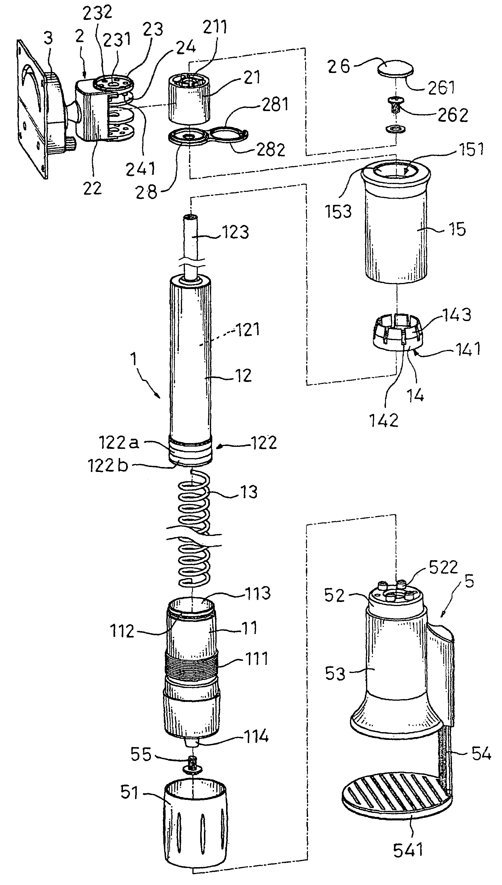
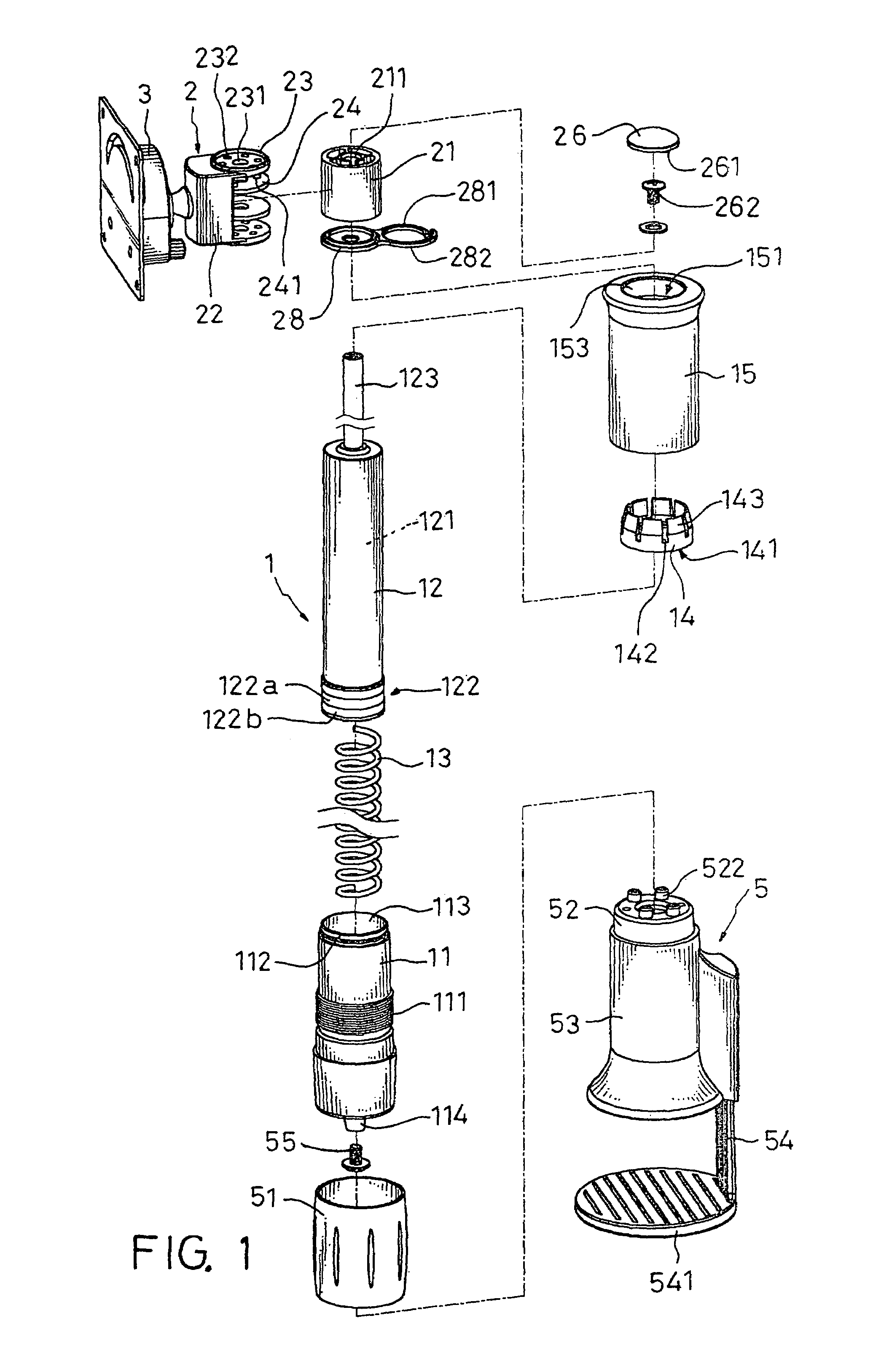
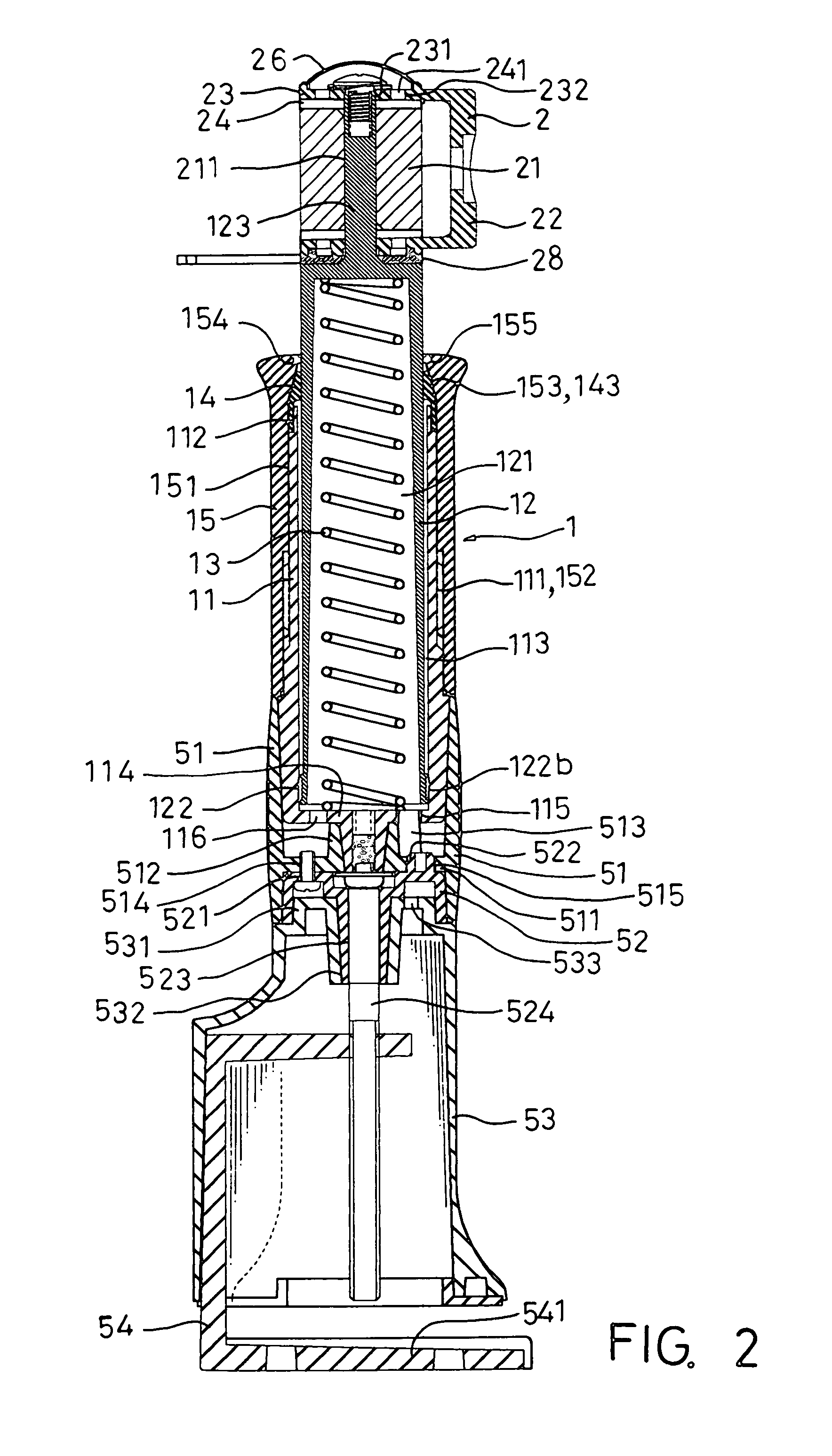
[0017]Referring to FIGS. 1 to 3, the present invention comprises a rising / descending device 1, a connecting axis 2 and a connecting mechanism 3.

[0018]The function of each component is described as following: The rising / descending device 1 further consists of an inner sleeve 11, a retractable shaft 12, an elastic body 13, a clip ring 14 and an outer sleeve 15. The inner sleeve 11 connects to a clip base 5 on the bottom; the clip base 5 clips to a stationary object, such as a table, a threads section 111 is on the middle of the inner sleeve 11 to connect to the outer sleeve 15, a fastening section 112 is on top of the inner sleeve 11 to connect to the clip ring 14, an inner chamber 113 is on the center of the inner sleeve 11 to position and contain the elastic body 13.

[0019]The retractable shaft 12 is inserted into the inner chamber 113, a hollow shaft chamber 121 contains the other end of the elastic body 13 that makes the retractable shaft 12 movable inside the inner sleeve 11. In o...


PUM


Abstract

A suspension arm comprising a rising / descending device further consists of an inner sleeve; a retractable shaft and an elastic body inside, an outer sleeve connect to the inner sleeve, a clip ring on the top open of the outer sleeve. The outer sleeve can revolve on the inner sleeve, when the user presses the clip ring to press or release the retractable shaft and make the retractable shaft rise or descend on top of the outer sleeve; a connecting axis is in torsion structure with a pillar shape connecting base and a central axis slot, an clip cover with two slices beside a compression ring stretching from top and bottom, all covered by the connecting base, a supporting axis of the retractable shaft passes the wedge holes of two slices, an axis slot in between and combines the supporting axis with a connecting device to wrap and compress the connecting base and let the clip cover revolvable; a connecting mechanism connects to the clip cover, the connecting mechanism connects the article to rise, descend; revolve and adjust in all directions with the rising / descending device.

Description

BACKGROUND OF THE INVENTION[0001]I. Field of the Invention[0002]This invention relates generally to a suspension arm and, more specifically, to a suspension arm that holds an article on one side, the other side is fixed on a stationary.[0003]II. Description of the Prior Art[0004]Heretofore, it is known that suspension arms are used in many places, such as paper shelves in the offices, telephone holders. The suspension arms can hold the articles and keep a height difference with the stationary, such scheme is very helpful for space arrangement.[0005]A good suspension arm in addition to hold articles, it must also be adjustable with the distance, turned right / left and up / down for different application and different users. All the manufacturers are working toward this goal to meet ergonomics requirement.[0006]New high technology products keep rolling out, such as flat panel displays, the LCD displays, LCD TV's gradually replace the traditional CRT TV's for flat panel displays have the ...

Claims


Application Information

Patent Timeline
Patent Type & Authority Patents(United States)
IPC IPC(8): A47F5/00F16M11/00B60G1/00F16M11/04F16M11/28F16M13/02
CPCF16M11/04F16M11/2014F16M11/28F16M13/02F16M13/022Y10S248/919F16M2200/024F16M2200/048F16M2200/068
Inventor LIN, CHIN-CHIH
Owner LIN CHIN CHIH
Learn More