
Magnetically navigable device with associated magnetic element

a magnetic element and navigable technology, applied in the field of magnetic navigable devices, can solve the problems of limited navigability and inability to control the degree of rotational freedom about the longitudinal axis magnetically, and achieve the effect of simplifying the navigability of the device and facilitating secure movement of the devi

Active Publication Date: 2007-02-27
SIEMENS HEALTHCARE GMBH
View PDF11 Cites 118 Cited by
  • Summary
  • Abstract
  • Description
  • Claims
  • Application Information

AI Technical Summary

Benefits of technology

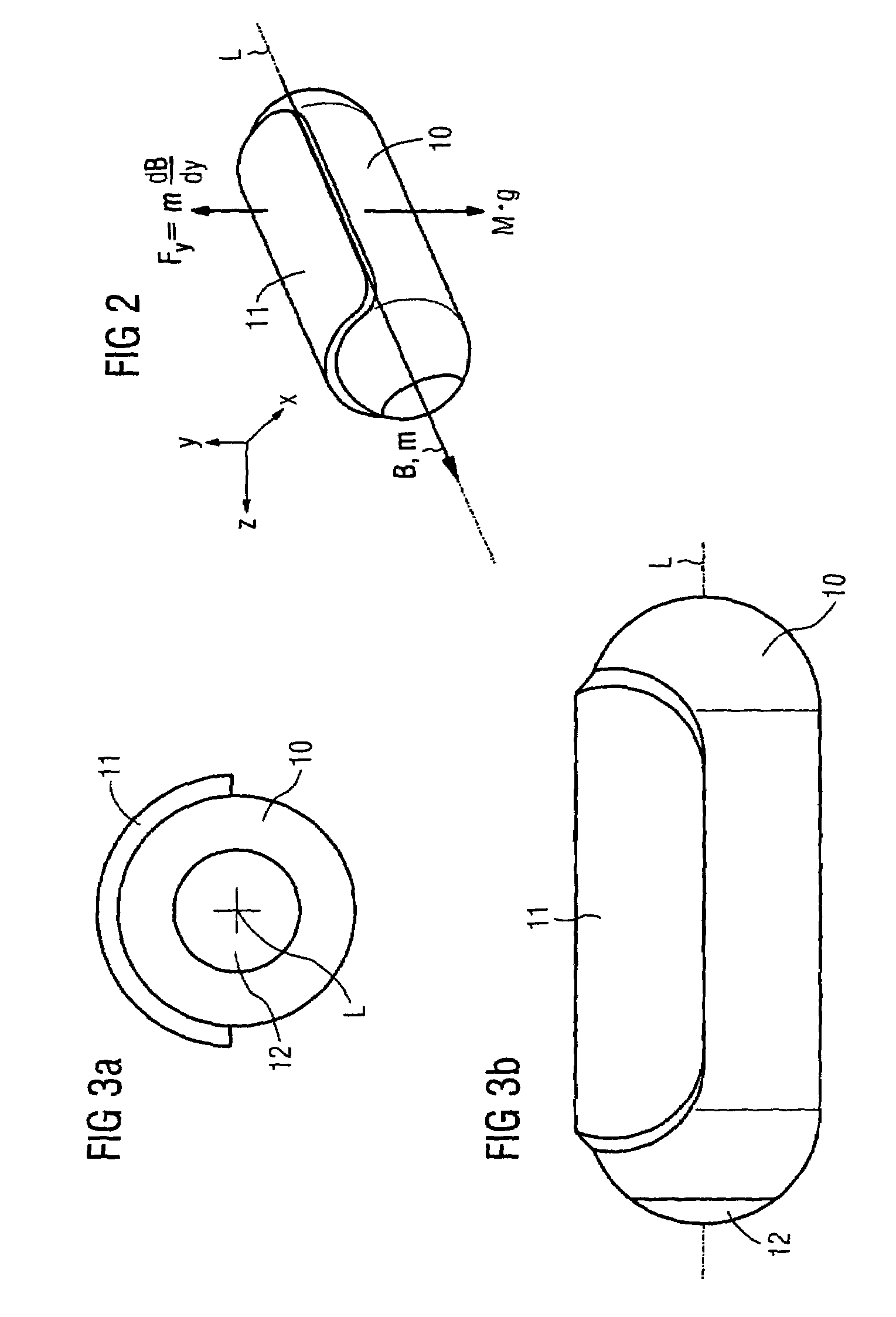
The present invention relates to a magnetically navigable device that can be easily identified and positioned in a magnetic field. The device contains a magnet element that is asymmetrically arranged, which causes the device to rotate in the magnetic field and align itself with the direction of the field lines. This rotation is caused by the magnetic force generated by the magnet element and the gravitational force engaging at the mass center of the device. The device can be easily identified and positioned in a video screen, which simplifies navigation. The device can also contain a support structure that is rotationally symmetrical, making it easy to design. The magnet element can be prefabricated and mounted externally or integrated into the device. The device can also contain shorted conductor loops for eddy current damping to prevent oscillations.

Problems solved by technology

However, the probe-like devices used in this context have only limited navigability, particularly at branch points, which means that contactless exertion of force from outside might entail an expansion of the field of application.
It is thus not possible to control the degree of rotational freedom about the longitudinal axis magnetically, however.

Method used


Image

  • Magnetically navigable device with associated magnetic element
  • Magnetically navigable device with associated magnetic element
  • Magnetically navigable device with associated magnetic element

Examples


Embodiment Construction

[0024]Reference will now be made in detail to the preferred embodiments of the present invention, examples of which are illustrated in the accompanying drawings, wherein like reference numerals refer to like elements throughout.

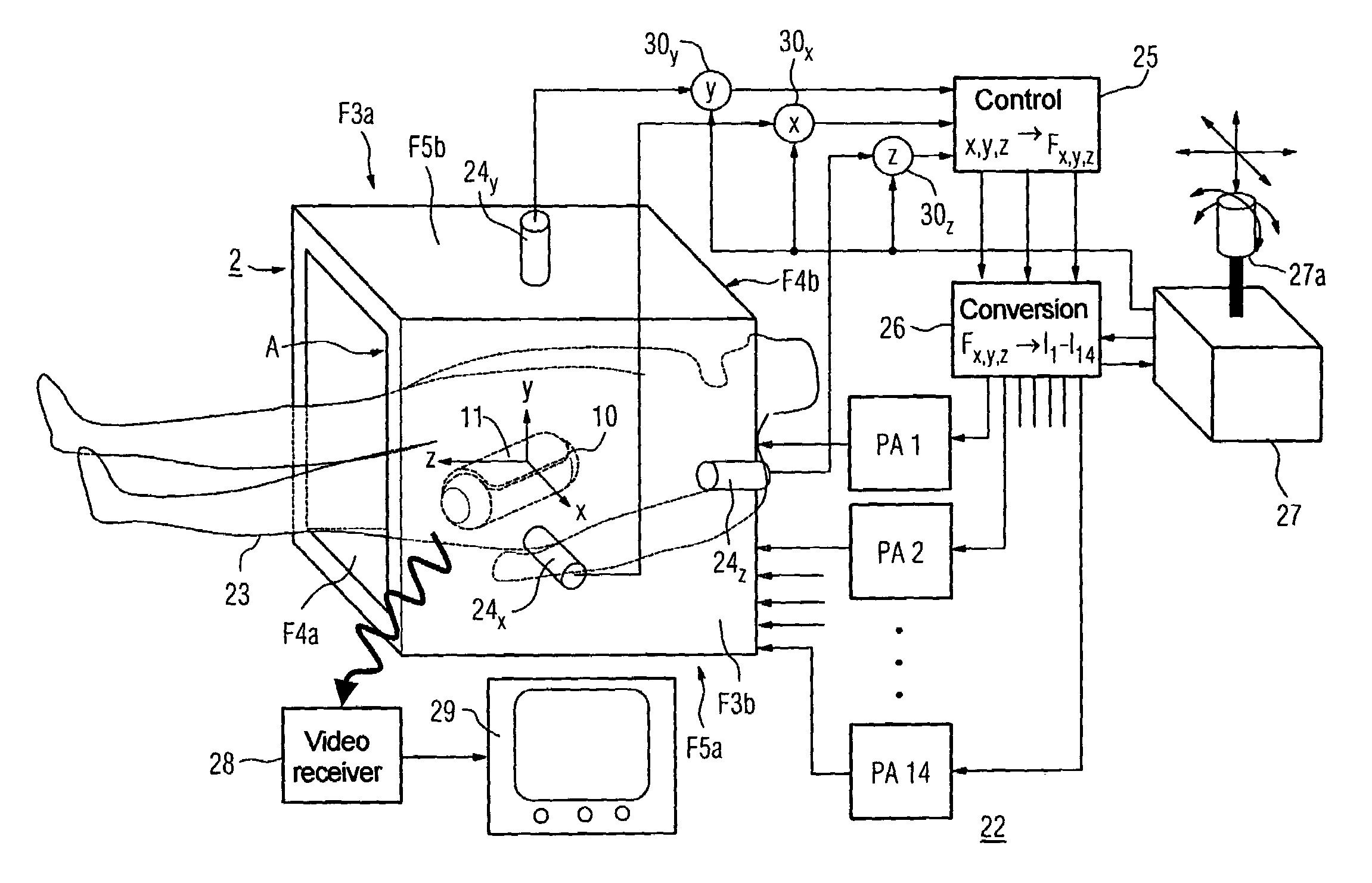
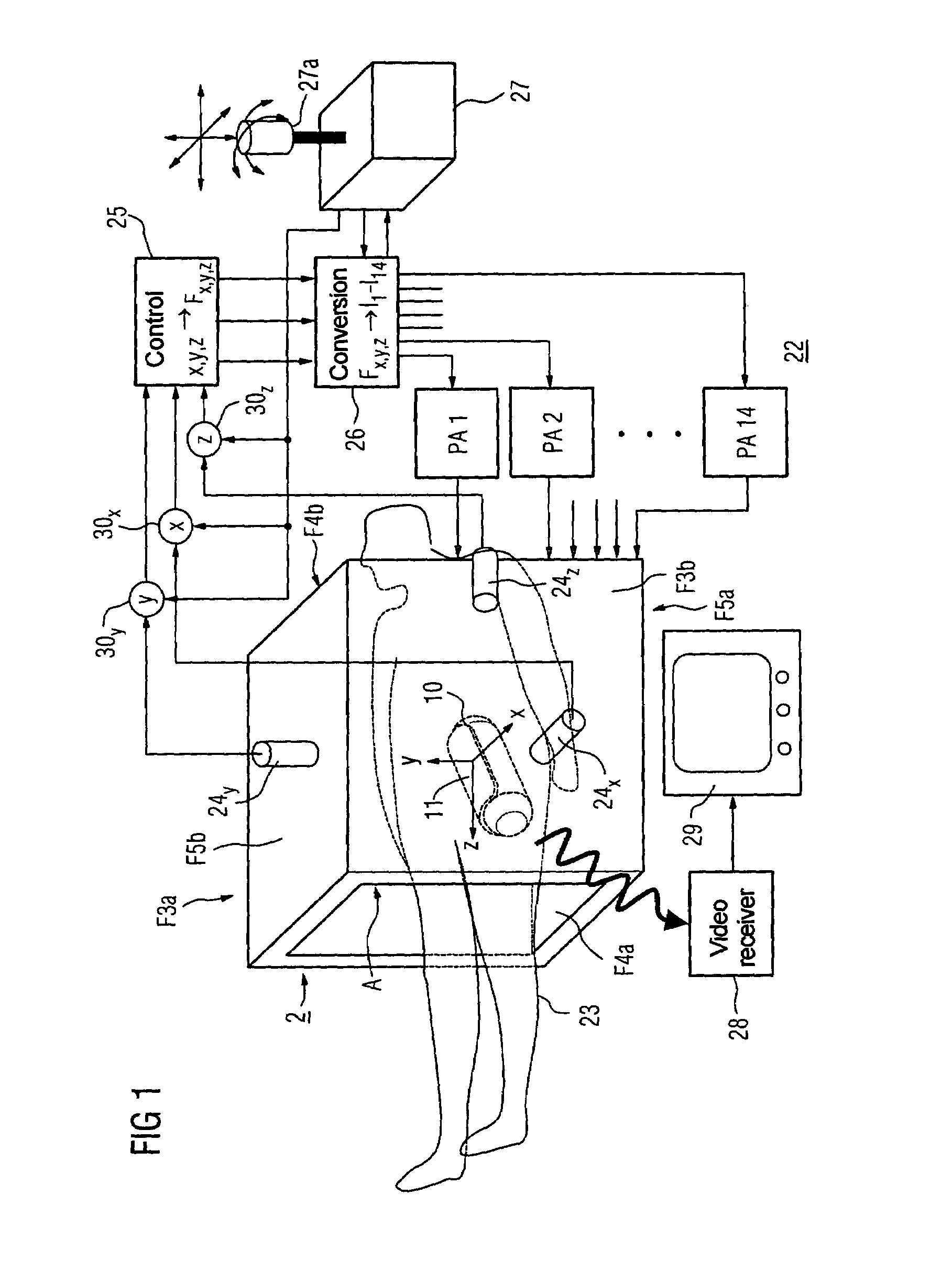
[0025]A device based on the invention basically includes a nonmagnetic support structure for at least one magnet element which is rigidly connected thereto or is integrated therein. The shape of the support structure is inherently arbitrary and is generally dependent on the respective instance of application. By way of example, the support structure, as assumed for the exemplary embodiment in FIG. 1, has an elongate shape in the direction of a longitudinal axis. By contrast, the magnet element connected thereto needs to have a form which is stretched in one direction. The corresponding pronounced extent of the element may preferably point in the direction of the longitudinal axis of the support structure. The device can move contactlessly in a working volume ...


PUM


Abstract

A magnetically navigable device has a magnet element with a greater extent in one direction than at right angles thereto. The magnet element is arranged asymmetrically with respect to a central axis of the device which points in the direction in which the magnet element extends. The device may be, for example, a video capsule from medical technology, such as for endoscopy.

Description

CROSS REFERENCE TO RELATED APPLICATIONS[0001]This application is based on and hereby claims priority to German Application No. 103 43 494.1 filed on 19 Sep. 2003, the contents of which are hereby incorporated by reference.BACKGROUND OF THE INVENTION[0002]1. Field of the Invention[0003]The invention relates to a magnetically navigable device with at least one associated magnet element which has a greater extent in one direction than at right angles thereto. The device can be assigned a central axis which points in this direction in which the magnet element extends. Such a magnetically navigable device can be found in DE 101 42 253 C1.[0004]2. Description of the Related Art[0005]In medicine, use is made of probe-like devices such as endoscopes or catheters which are inserted into a proband through incisions or body orifices and can be displaced externally in the longitudinal direction and hence can be navigated in one dimension. Optical fibers permit visual inspection, with control wi...

Claims


Application Information

Patent Timeline
Patent Type & Authority Patents(United States)
IPC IPC(8): A61B19/00A61B5/05A61B5/07A61B1/00A61B5/06
CPCA61B1/00147A61B1/00158A61B5/06A61B1/041A61B2019/2261A61B2019/2253A61B34/73A61B2034/732A61B5/062
Inventor RIES, GUNTER
Owner SIEMENS HEALTHCARE GMBH
Learn More