Dental contact matrix limited

a contact matrix and limited technology, applied in the field of dental contact matrix, can solve problems such as cumbersome placement of matrices

Inactive Publication Date: 2007-02-13
DENTSPLY SIRONA INC
View PDF23 Cites 22 Cited by
  • Summary
  • Abstract
  • Description
  • Claims
  • Application Information

AI Technical Summary

Benefits of technology

[0007]It is therefore an object of the present invention to provide a system for securing dental matrices which is an improvement on the prior art systems and devices or which will at least provide the industry with a useful choice.

Problems solved by technology

The use of separate components makes it cumbersome to place matrices and requires the dental professional to undertake multiple steps in order to secure the matrix.

Method used


Image

  • Dental contact matrix limited
  • Dental contact matrix limited
  • Dental contact matrix limited

Examples


Embodiment Construction

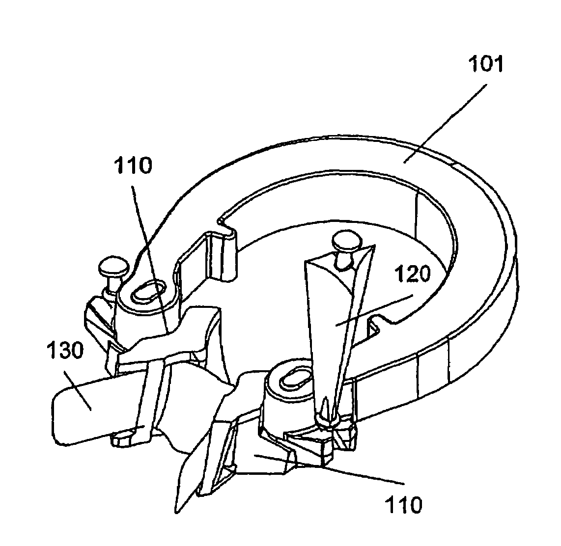
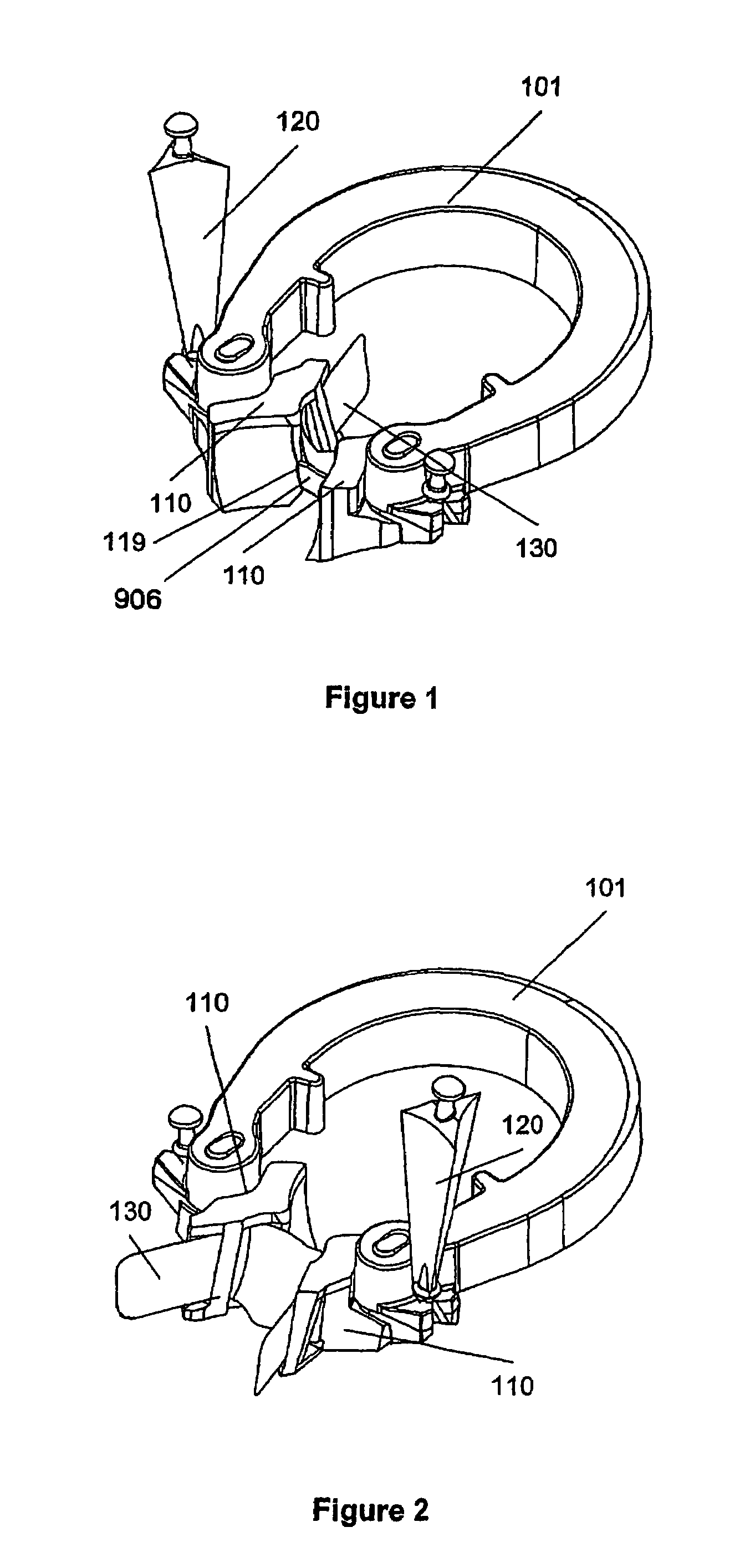
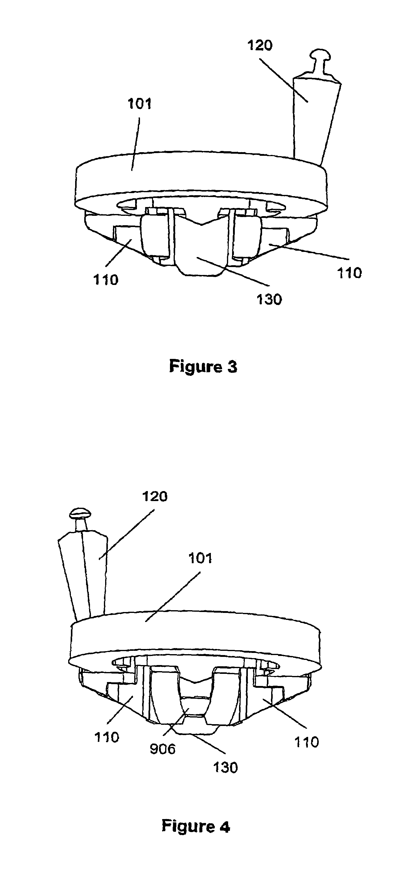
[0052]Referring to FIGS. 1 and 4 there is shown the dental contact matrix system according to the most preferred embodiment of the present invention. The dental contact matrix system includes a retainer with a spring 101 and two lugs 110 attached to the spring 101. A matrix 130 is held in place by lugs 110 and an elastic wedge 120 is wrapped under the two lugs 110 and the spring 101.

[0053]The retainer includes means for receiving and holding the elastic wedge in a stretched condition. The preferred means include a guide on each lug in the form of channels 119. Preferably the means also include a wedge engagement associated with each lug. In the preferred embodiment these are cleats 105.

[0054]Referring to FIG. 7 spring 101 is generally semi circular or U-shaped in plane view. Referring to FIGS. 5 to 8 the spring has two arms 102 under tension. The arms 102 require force to push them apart. The dental professional pushes the arms 102 apart using rubber dam forceps or another similar t...


PUM


Abstract

A dental contact matrix system is described for the placement of dental fillings. The dental contact matrix system includes a matrix, a retainer for placing and retaining the 5 matrix and an elastic wedge. The retainer includes two lugs or tines that fit between two teeth on the buccal and lingual sides of the teeth. The lugs are connected by spring member that presses the lugs against the lingual and buccal sides of the teeth. There is an adaptation to hold the elastic wedge in a stretched condition between the lugs.

Description

[0001]This is a nationalization of PCT / IB02 / 04824 filed Nov. 19, 2002 and published in English.[0002]1. Field of the Invention[0003]The present invention relates to an apparatus for the placement of dental fillings and in particular light curable dental fillings.[0004]2. Summary of the Prior Art[0005]The dental profession has moved over the last two or so decades from the use of mercury based fillings to the use of composite resins that are used to provide natural looking fillings. Composite resin is cured by the application of concentrated light. To enable the dental professional to place composite resin fillings matrixes are used. A matrix which is a device which wraps around the tooth and acts as a mould to contain the composite resins before they are cured. Matrices are generally formed of plastic or stainless steel and are either circumferential or sectional. Sectional matrices fit only in one proximal area of the tooth while circumferential matrix bands fit around the entire c...

Claims


Application Information

Patent Timeline
Patent Type & Authority Patents(United States)
IPC IPC(8): A61C3/00A61C5/12A61C5/04A61C7/00A61C19/00
CPCA61C5/127A61C5/125A61C5/85A61C5/88
Inventor MCDONALD, SIMON PAUL
Owner DENTSPLY SIRONA INC
Why Eureka
Try Eureka