
Digital engine hour meter for outdoor power equipment

an engine hour meter and digital technology, applied in electromechanical unknown time interval measurement, instruments, horology, etc., can solve the problems of premature indication of maintenance need, inaccurate measurement of engine use, and overstate the true engine operating hours

Active Publication Date: 2006-12-26
DELTA SYST
View PDF8 Cites 20 Cited by
  • Summary
  • Abstract
  • Description
  • Claims
  • Application Information

AI Technical Summary

Benefits of technology

The solution provides accurate engine operating hour tracking, eliminating unnecessary counting when the engine is not running, and ensuring compatibility with both AC and DC signals, while being compact and requiring minimal maintenance.

Problems solved by technology

Such hour meters provide an inaccurate measure of engine use.
There may be instances where the ignition switch is on and the engine is not running, for example, an operator may inadvertently leave the ignition key in the on position after use of the equipment is completed and the engine is off.
If the hour meter is accumulating time when the ignition switch is on the accumulated hours on the hour meter will overstate the true engine operating hours.
Since warranty and service intervals are generally based on hours of engine operation, accumulating hours on the hour meter when the ignition key is on will result in premature indication that maintenance is needed and / or premature expiration of warranty, both to the disadvantage and dissatisfaction of the equipment owner.
A disadvantage of such three terminal hour meters is that they necessarily include three terminals, two for power and a third terminal which must be enabled for accumulation of time.
An additional disadvantage of the three terminal hour meter with an internal power source is that the power source eventually runs down necessitating a new power source being installed.

Method used


Image

  • Digital engine hour meter for outdoor power equipment
  • Digital engine hour meter for outdoor power equipment
  • Digital engine hour meter for outdoor power equipment

Examples


Embodiment Construction

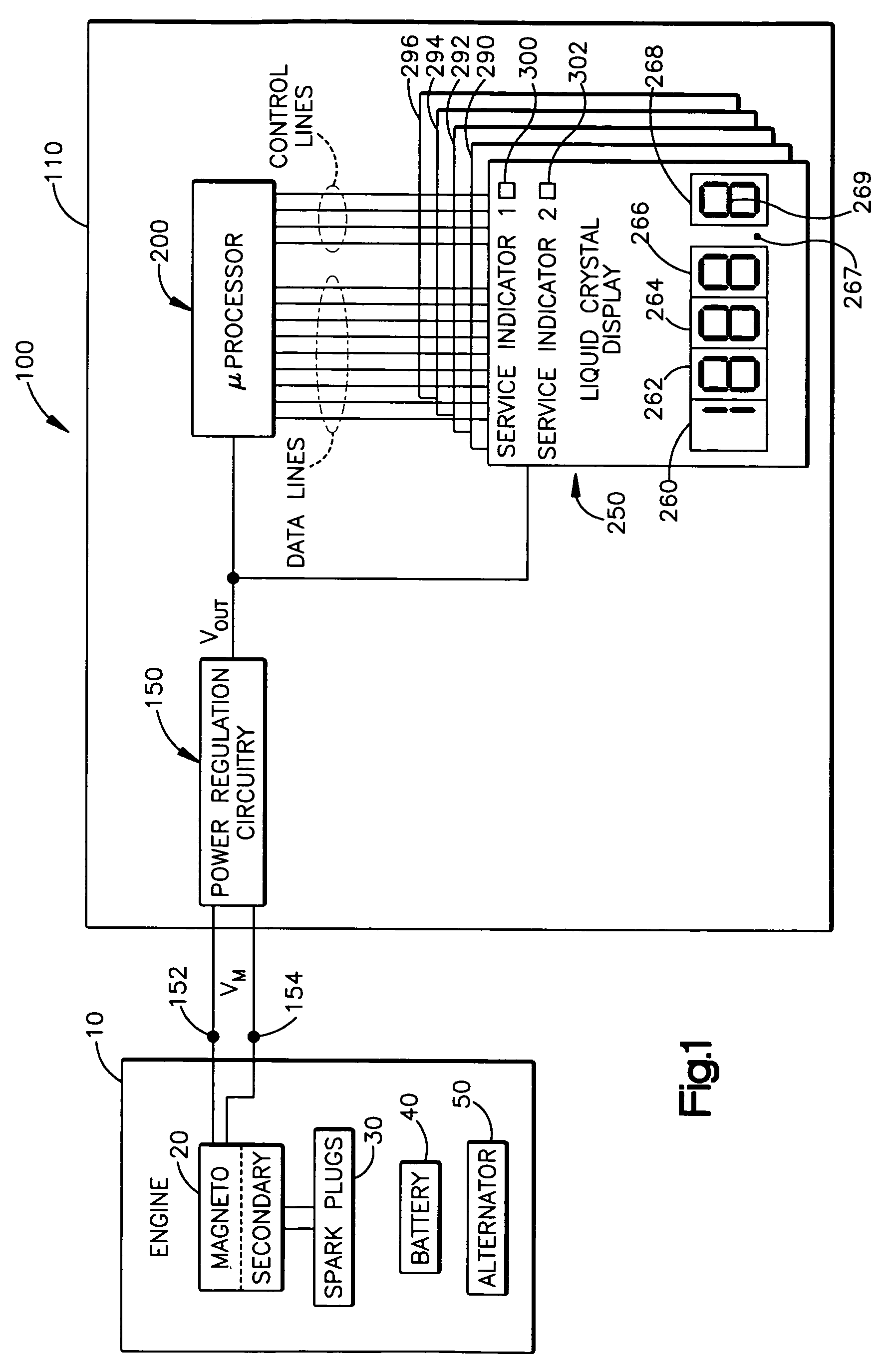
[0018]Turning to the drawings, a block diagram of an a digital engine operating time measuring apparatus of the present invention is shown generally at 100 in FIG. 1. The apparatus 100, which will be referred to herein as an hour meter, is normally used in conjunction with a piece of outdoor power equipment or vehicle including an internal combustion engine 10. The hour meter 100 displays, via a liquid crystal display 250, an accumulated time in hours that the engine has been operated.

[0019]Typically, the hour meter 100 is mounted on a dashboard of outdoor power equipment such as a tractor, snowmobile, riding lawn mower, personal water craft or boat to inform the owner of the number of hours that the engine has been operated since the equipment was manufactured. However, it should be understood that the hour meter 100 of the present invention can be utilized with any type of internal combustion engine and is not limited to any particular type of equipment or vehicle. For ease of ins...


PUM


Abstract

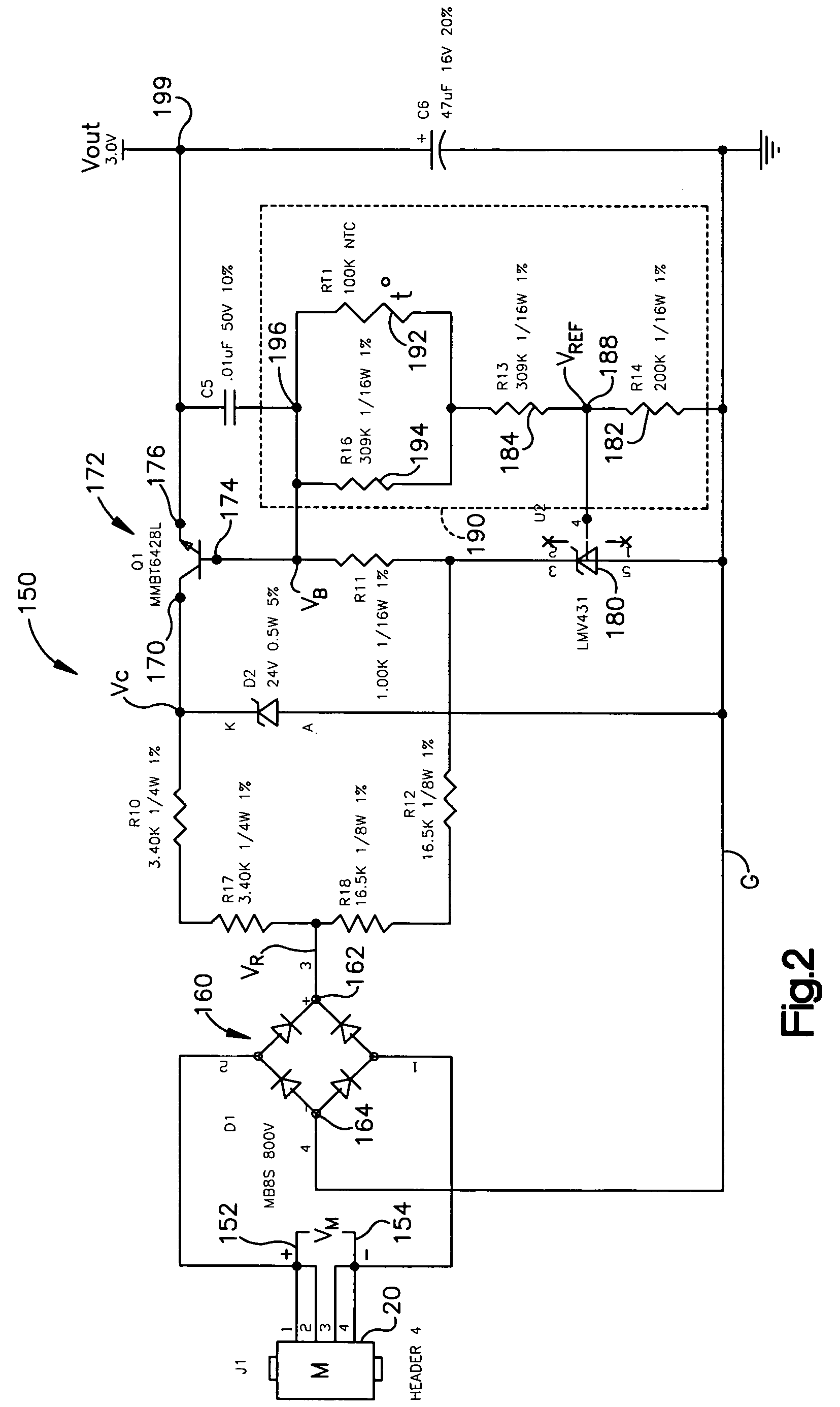
A digital engine operating time measuring apparatus for an internal combustion engine. The apparatus is powered by a magneto of the engine and accumulates engine operating time only when the engine is operating. The apparatus includes power regulation circuitry including a pair of terminals coupled to the engine magneto. The power regulation circuitry converts a time varying electrical signal generated by the magneto when the engine is operating to a low voltage DC signal. The apparatus further includes digital circuitry coupled to an output of the power regulation circuitry for calculating accumulated engine operating time. The digital circuitry is powered by the low voltage DC signal of the power regulation circuitry and only accumulates engine operating time upon sensing the low voltage DC signal. The apparatus further includes a display coupled to the digital circuitry for displaying accumulated engine operating time as calculated by the digital circuitry.

Description

FIELD OF THE INVENTION[0001]The present invention relates to an hour meter for outdoor power equipment and, more particularly, a digital hour meter for outdoor power equipment that is powered by a magneto of an internal combustion engine and accumulates engine operating time only when the engine is actually operating.BACKGROUND ART[0002]Engine operating time hour meters for outdoor power equipment including riding lawn mowers, lawn and agricultural tractors, snowmobiles, snowblowers, jet skis, boats, all terrain vehicles, bulldozers, generators, etc. are well known. Such engine operating time hour meters are provided, among other things, to let the owner and / or manufacturer know how long the equipment has been operated, when the equipment is due for repair / maintenance service, whether the equipment is still under warranty, etc.[0003]With the widespread use of digital circuitry, digital engine operating time hour meters generally have replaced the old style mechanical hour meters whi...

Claims


Application Information

Patent Timeline
Patent Type & Authority Patents(United States)
IPC IPC(8): G04F8/00G04F10/00G04F10/10
CPCG04F10/10
Inventor STRAKA, DAVID A.
Owner DELTA SYST
Learn More