
Light interference measurement method using computer-generated hologram, and interferometer using this method

a technology of light interference and measurement method, which is applied in the direction of instruments, measurement devices, and optical means, can solve the problems of loss of measurement meaning and inability to accurately measure, and achieve the effect of adjusting the relative position relationship and high degree of precision

Inactive Publication Date: 2006-12-05
FUJI PHOTO OPTICAL CO LTD
View PDF4 Cites 7 Cited by
  • Summary
  • Abstract
  • Description
  • Claims
  • Application Information

AI Technical Summary

Benefits of technology

"The present invention provides a light interference measurement method and interferometer using a computer-generated hologram that can accurately measure the surface shape of a sample using interference fringes obtained by light wave interference between a reference light and an object light. The invention addresses the problem of positional deviation between the computer-generated hologram and the sample surface, which can cause interference fringes and thus affect the accuracy of the measurement. The invention provides a solution for easy and precise adjustment of the relative positions of the computer-generated hologram and the sample surface, ensuring accurate measurement. The invention also includes a retaining member and a spacer for position adjustment, and a switching apparatus and imaging apparatus for ensuring precise alignment and measurement."

Problems solved by technology

If this adjustment is even slightly insufficient, so that a positional deviation is generated between these two parts, interference fringes corresponding to this positional deviation will be generated, so that accurate measurement becomes impossible, and the meaning of the measurement is lost.

Method used


Image

  • Light interference measurement method using computer-generated hologram, and interferometer using this method
  • Light interference measurement method using computer-generated hologram, and interferometer using this method
  • Light interference measurement method using computer-generated hologram, and interferometer using this method

Examples


Embodiment Construction

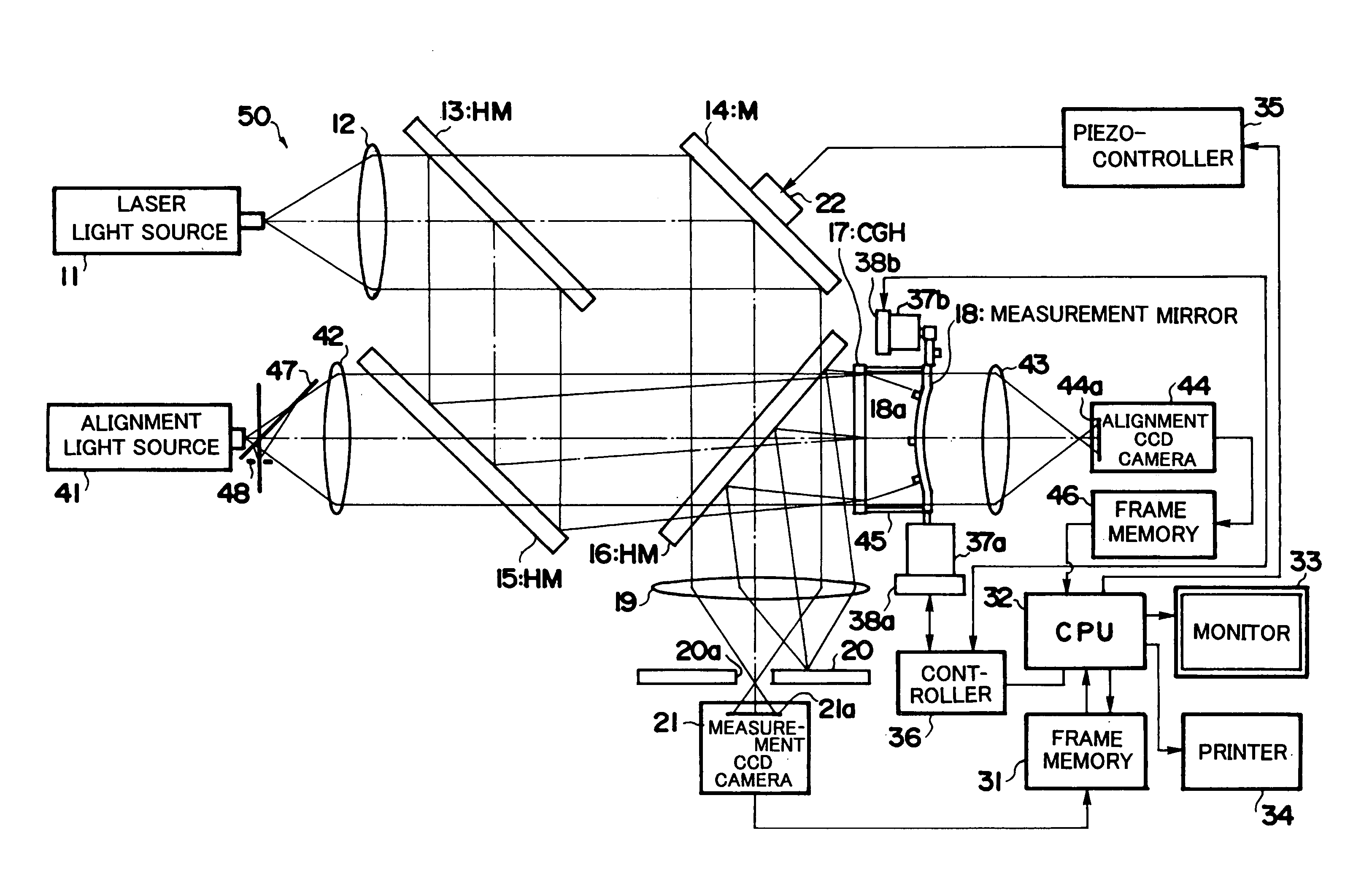
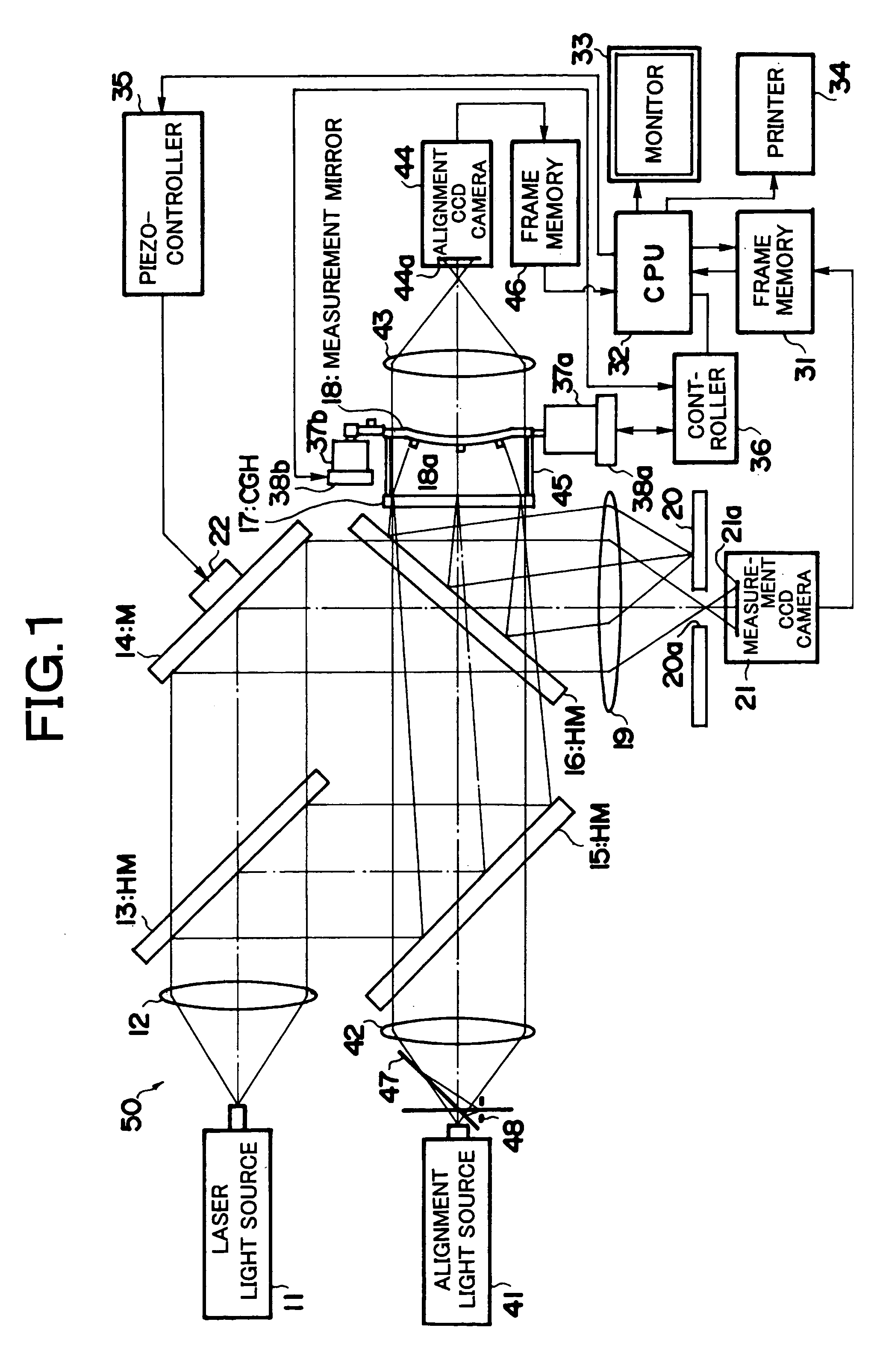
[0031]Embodiments of the present invention will be described below with reference to the attached figures. FIG. 1 is a schematic drawing which shows an interferometer constituting one embodiment of the present invention.

[0032]The interferometer 50 shown in FIG. 1 is formed as a Mach-Zender type interferometer like the interferometer of the prior art illustrated in FIG. 4. Like the conventional interferometer, this interferometer comprises a main measurement optical system that measures the surface shape of a measurement mirror (this is also referred to an object). However, the characterizing feature of the interferometer 50 of this embodiment is that this interferometer comprises an alignment optical system that is combined with this main measurement optical system. Accordingly, the alignment optical system in particular will be described in detail, and only a brief description of the main measurement optical system will be given.

[0033]In this interferometer 50, diffused light that ...


PUM


Abstract

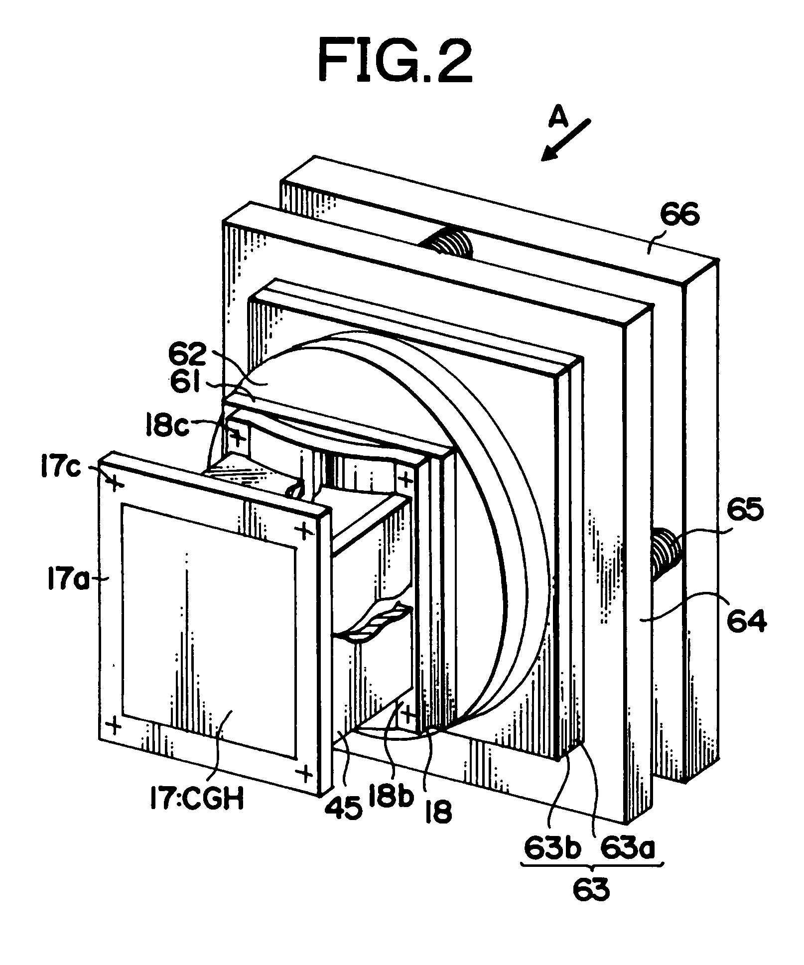
The present invention makes it possible to reliably hold a computer-generated hologram 17 and a sample surface 18a in ideal design positions and to perform interference measurements on the surface shape of the sample surface 18a by holding the computer-generated hologram 17 in a predetermined attitude by using a retaining member, and interposing a spacer 45 between this retaining member and the object so that relative positioning of both the computer-generated hologram 17 and the sample surface 18a is performed. Light transmission type targets used for alignment are respectively disposed on the four corners of the frame body of the CGH 17 and the four corners of the measurement mirror 18, and the system is devised so that images of these targets can be obtained by an image focusing lens 43 and CCD camera 44, thus making it possible to check the adjustment of the alignment of the CGH 17 and sample surface 18a.

Description

RELATED APPLICATION[0001]This application claims the priority of Japanese Patent Application No. 2003-397327, which is incorporated herein by reference.BACKGROUND OF THE INVENTION[0002]1. Field of the Invention[0003]The present invention relates to an alignment method in interference measurements using a hologram, and an interferometer using this method. More particularly, the present invention relates to a light interference measurement method using a computer-generated hologram in which, when the surface shape of an aspherical mirror or the like is measured using an interferometer, the object and a hologram that is disposed in the optical path of the illuminating light beam directed onto the object are set in a predetermined positional relationship, and an interferometer using this method.[0004]2. Description of the Prior Art[0005]In recent years, methods have become known in which aspherical surfaces are formed on predetermined surfaces of optical members in order to make it poss...

Claims


Application Information

Patent Timeline
Patent Type & Authority Patents(United States)
IPC IPC(8): G01B9/021G01B11/02G01B9/02G01B9/023G01B11/24G03H1/00G03H1/08
CPCG01B9/023G01B11/2441G03H1/0005G03H1/08G03H2001/0033G03H2001/0066G03H2001/0072
Inventor YASUDA, KENJIMATSUDA, SHINICHI
Owner FUJI PHOTO OPTICAL CO LTD
Learn More