Locking device for a storage cabinet

a storage cabinet and locking device technology, applied in the field of locking devices, can solve the problems of inconvenient method of using complex structure of a conventional locking device, and achieve the effect of simple and convenient us

Inactive Publication Date: 2006-11-07
CHANG HSUEH LIANG
View PDF7 Cites 24 Cited by
  • Summary
  • Abstract
  • Description
  • Claims
  • Application Information

AI Technical Summary

Benefits of technology

[0006]The primary objective of the present invention is to provide a locking device for a storage cabinet that is simple and convenient to use.
[0008]When the locking device is used, the card is inserted into the card slot to operate the locking device, replacing the usual coins. The key is then rotated to lock or unlock the door. This method of using a card for the operation of the locking device provides a simple and convenient way to use a pay storage locker.

Problems solved by technology

The structure of a conventional locking device is very complex and coins are almost always required to operate the locking device.
The method of using a conventional locking device is inconvenient.

Method used


Image

  • Locking device for a storage cabinet
  • Locking device for a storage cabinet
  • Locking device for a storage cabinet

Examples


Embodiment Construction

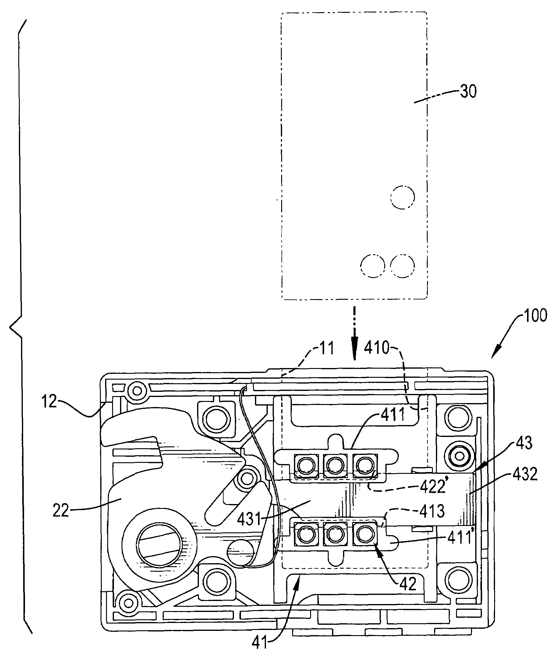
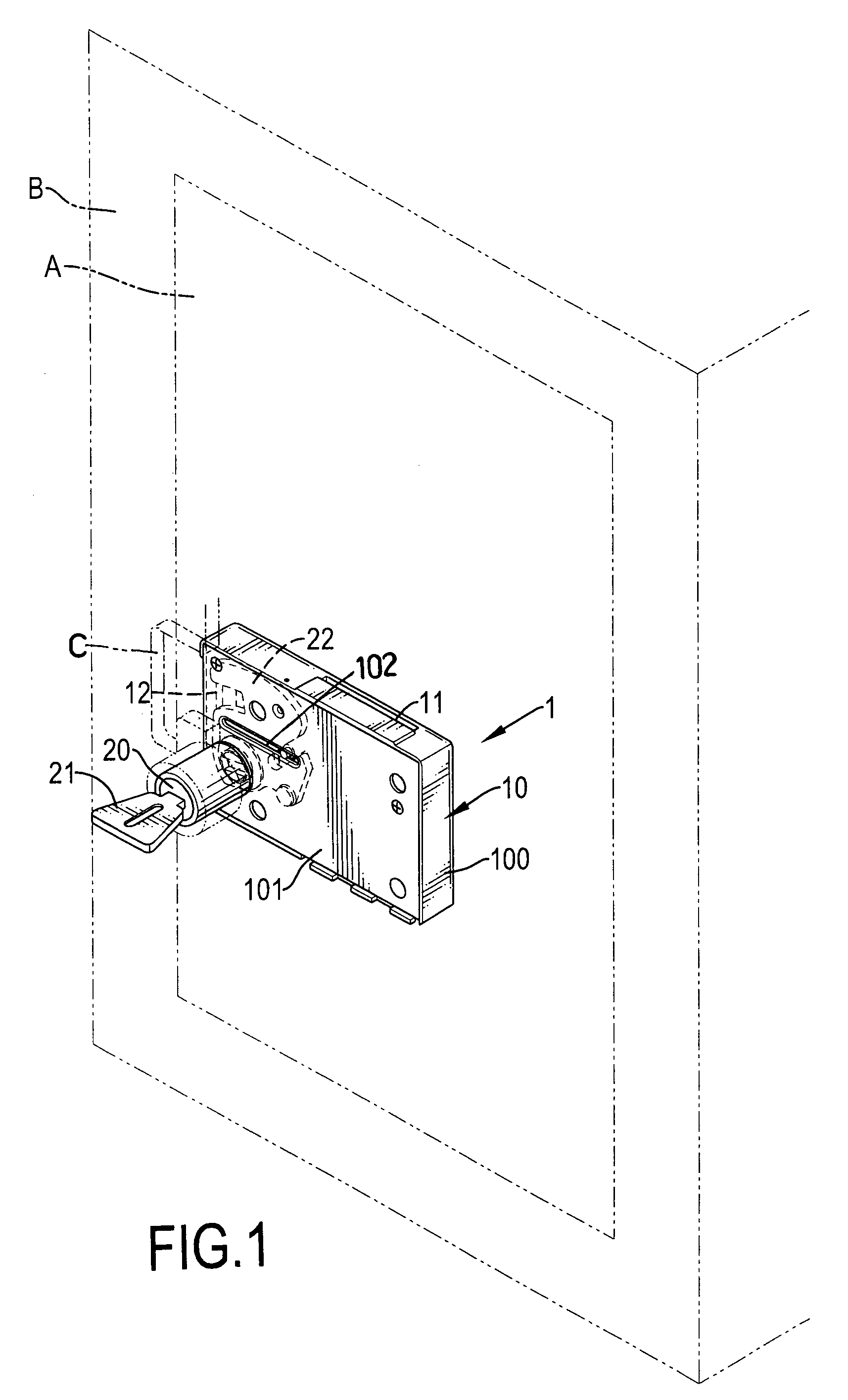
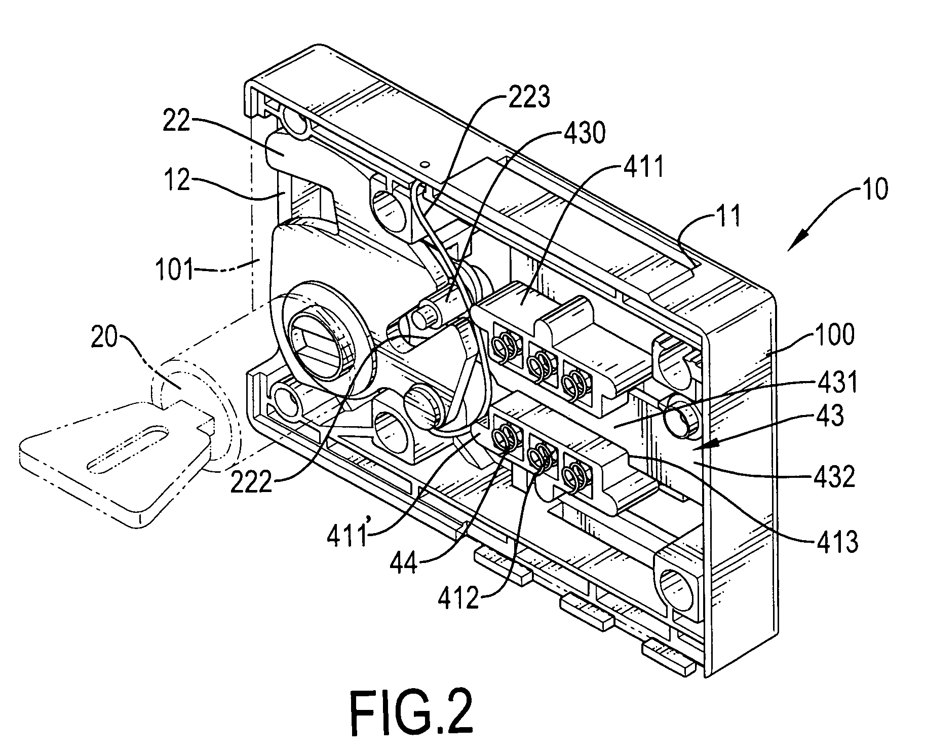
[0017]With reference to FIGS. 1 to 3, a locking device (1) for a cabinet in accordance with the present invention has a body (10), a cylinder and a card (30). The cabinet has a door (A), a cabinet body (B) and a hook (C). The door (A) has an inner surface and an outer surface. The hook (C) is defined in the cabinet (B) and faces the door (A). The locking device (1) is mounted on the door (A).

[0018]The body (10) has a case (100), a cap (101) and a controlling device (40). The case (100) has a top surface, two side surfaces, a bottom surface, a front opening, an inner rear wall, an inner edge, a card slot (11), a breach (12) and two optional recesses (13). The card slot (11) is defined in the top surface of the case (100). The breach (12) is defined in one of the side surfaces of the case (100). The recesses (13) are defined in the inner rear wall of the case (100) and are parallel to each other.

[0019]The cap (101) is mounted on the front opening of the case (100) and has a horizontal...


PUM


Abstract

A locking device for a storage cabinet that has a door, a cabinet body and a hook defined in the cabinet body facing the door. The locking device mounted on the door. The locking device has a body, a cylinder and a card. The body has a case, a cap and a controlling device. The case has a card slot. The cap is mounted on the case. The controlling device is mounted inside the case and connects to the cylinder. The cylinder has a cylinder body with a keyhole and a key. The card can be inserted into the card slot. When the card is inserted into the card slot, the key can be rotated to operate the lock. The method of using a card instead of coins for the operation a locking device provides convenience.

Description

BACKGROUND OF THE INVENTION[0001]1. Field of the Invention[0002]The present invention relates to a locking device, more particularly to a locking device for a storage cabinet.[0003]2. Description of the Related Art[0004]Many public places provide lockable storage cabinets, or lockers, for use by the general public and most of these lockers require payment for use. A conventional pay locker has a cabinet body and a locking device. The cabinet has a door. The locking device is mounted on the door of the cabinet. When a coin is put in the locking device, the locking device can be operated. The structure of a conventional locking device is very complex and coins are almost always required to operate the locking device. The method of using a conventional locking device is inconvenient.[0005]Thus, a real need exists for a locking device for a storage cabinet that is simple and convenient to use.SUMMARY OF THE INVENTION[0006]The primary objective of the present invention is to provide a lo...

Claims


Application Information

Patent Timeline
Patent Type & Authority Patents(United States)
IPC IPC(8): E05B65/06E05B21/00
CPCE05B35/007E05B35/086Y10T70/7198Y10T70/7531Y10T70/7232Y10T70/7192Y10T70/5341
Inventor CHANG, HSUEH-LIANG
Owner CHANG HSUEH LIANG
Why Eureka
Try Eureka