
Apnea/hypopnea detection system and method

a detection system and apnea technology, applied in the field of apnea/hypopnea detection system, can solve the problems of sleep apnea sufferers being at risk for excessive mortality, sleep fragmentation, and possible severe degrees of oxyhemoglobin desaturation, and achieve high-precision measurement of patient flow and accurate a/h detection

Active Publication Date: 2006-10-10
RIC INVESTMENTS LLC
View PDF38 Cites 49 Cited by
  • Summary
  • Abstract
  • Description
  • Claims
  • Application Information

AI Technical Summary

Benefits of technology

"The present invention provides an apnea / hypopnea detection system and method that overcomes the shortcomings of conventional techniques. The system includes a flow sensor and processor that calculates parameters based on the patient's respiratory flow. These parameters are then compared with a long term threshold to determine if the patient is experiencing an apnea / hypopnea. The system does not require a highly accurate measurement of the patient's flow and can detect apnea / hypopnea without distinguishing between the inspiratory and expiratory phases of the respiratory cycles. The system can be used in an auto-titration pressure support system to control the pressure delivered to the patient based on whether or not they are experiencing apneas / hypopneas."

Problems solved by technology

Those afflicted with sleep apnea experience sleep fragmentation and complete or nearly complete cessation of ventilation intermittently during sleep with potentially severe degrees of oxyhemoglobin desaturation.
Sleep apnea sufferers may be at risk for excessive mortality from these factors as well as by an elevated risk for accidents while driving and / or operating potentially dangerous equipment.
Even if a patient does not suffer from a complete or nearly complete obstruction of the airway, it is also known that adverse effects, such as arousals from sleep, can occur where there is only a partial obstruction of the airway.
Partial obstruction of the airway typically results in shallow breathing referred to as a hypopnea.
This often requires detecting the airflow accurately, which can be difficult in some conditions, for example, if the airflow is being measured via a nasal cannula and the patient is experiencing mouth breathing.
Although techniques exist for distinguishing between the inspiratory and the expiratory states of a patient, this remains a complicated task and is subject to errors.

Method used


Image

  • Apnea/hypopnea detection system and method
  • Apnea/hypopnea detection system and method
  • Apnea/hypopnea detection system and method

Examples


Embodiment Construction

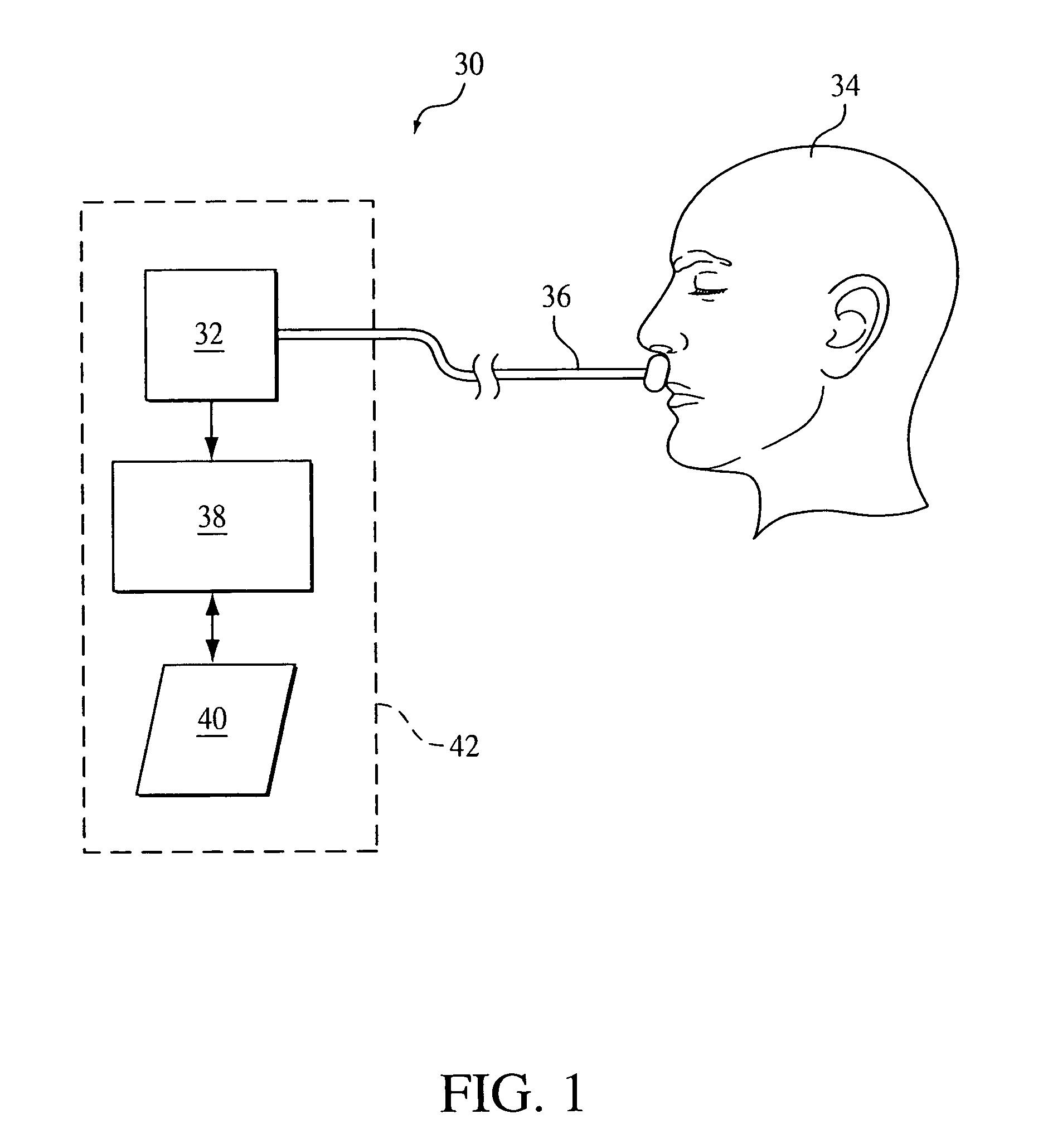
[0021]FIG. 1 schematically illustrates an exemplary embodiment of an apnea / hypopnea (A / H) detection system 30 according to the principles of the present invention. In its most basic form, detection system includes a sensor 32 in communication with the airway of a patient 34 to measure the flow of gas into and out of the patient, which is referred to as respiratory flow. In the illustrated embodiment, sensor 32 is a conventional flow sensor, such as a differential pressure sensor that communicates with the airway of the patient via a nasal cannula 36.

[0022]It is to be understood that the present invention contemplates using any conventional technique for detecting the patient's respiratory flow. For example, the present invention contemplates using the flow sensing technology taught in U.S. Pat. Nos. 6,017,315; 6,342,040; and 6,554,192 all to Starr et al. The present invention also contemplates using a conventional flow sensor, such as a pneumotach, coupled to the patient's airway vi...


PUM


Abstract

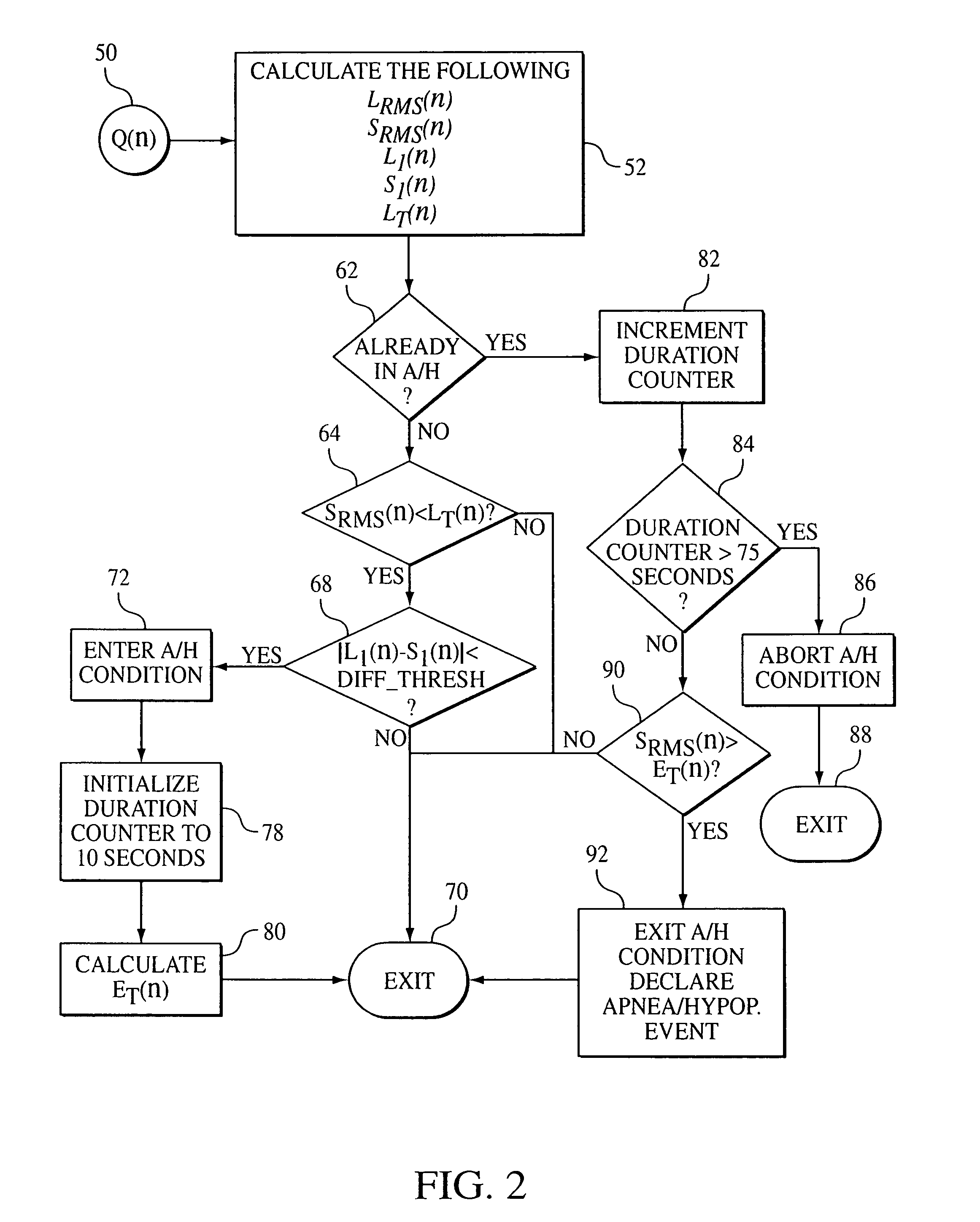
An apnea / hypopnea detection system and method that monitors a patient's respiratory flow, determines (a) a long term RMS energy based on the flow, (b) a long term threshold determined based on the long term RMS energy, and (c) a short term RMS energy based on the flow. Determining whether the patient is experiencing an apnea / hypopnea is accomplished by comparing the short term RMS energy with the long term threshold. This A / H detection technique is useful in diagnosing a patient for a breathing disorder, such as OSA, and / or for controlling an auto-titration pressure support system.

Description

CROSS-REFERENCE TO RELATED APPLICATIONS[0001]This application claims priority under 35 U.S.C. § 119(e) from provisional U.S. patent application No. 60 / 490,173 filed Jul. 25, 2003 the contents of which are incorporated herein by reference.BACKGROUND OF THE INVENTION[0002]1. Field of the Invention[0003]The present invention pertains to a system and method for detecting apnea / hypopnea events, and, in particular, to an apnea / hypopnea detection technique based on comparing a root-mean-square (RMS) of a patient's respiratory flow to a target value.[0004]2. Description of the Related Art[0005]Many individuals suffer from disordered breathing during sleep. Sleep apnea is a common example of such disordered breathing suffered by millions of people throughout the world. One type of sleep apnea is obstructive sleep apnea (OSA), which is a condition in which sleep is repeatedly interrupted by an inability to breathe due to an obstruction of the airway; typically the upper airway or pharyngeal a...

Claims


Application Information

Patent Timeline
Patent Type & Authority Patents(United States)
IPC IPC(8): A61B5/08A61M16/00A61B5/087
CPCA61B5/087A61B5/4818
Inventor HABERLAND, BENSHANKAR, UDAY S
Owner RIC INVESTMENTS LLC
Learn More