
Waste container

a technology for waste containers and containers, applied in the field of containers, can solve the problems of inconvenient lifting of waste containers, unsuitable handles for pulling waste containers on wheels,

Inactive Publication Date: 2006-10-03
REHRIG PACIFIC CO INC
View PDF32 Cites 36 Cited by
  • Summary
  • Abstract
  • Description
  • Claims
  • Application Information

AI Technical Summary

Benefits of technology

The present invention is a waste container with a movable handle that can be positioned close to the upper edge of the side wall for emptying into a truck hopper or at a greater distance for pulling on wheels. The handle has two arms pivotable about a single pivot point on the side wall, which can be rotated to different positions for different uses. The shorter arm is convenient for emptying into a truck hopper and the longer arm is convenient for pulling on wheels. The technical effect of this invention is to provide a convenient and efficient waste container for emptying and pulling, with a movable handle that can be easily positioned for different uses.

Problems solved by technology

While these handles are useful for lifting the waste container, such as for emptying the waste container into the hopper of a truck, these handles are not well-suited for pulling the waste container on the wheels.
Longer handles are more suited to pulling the waste container on the wheels, but inconvenient for lifting the waste container.

Method used


Image

  • Waste container
  • Waste container
  • Waste container

Examples


Embodiment Construction

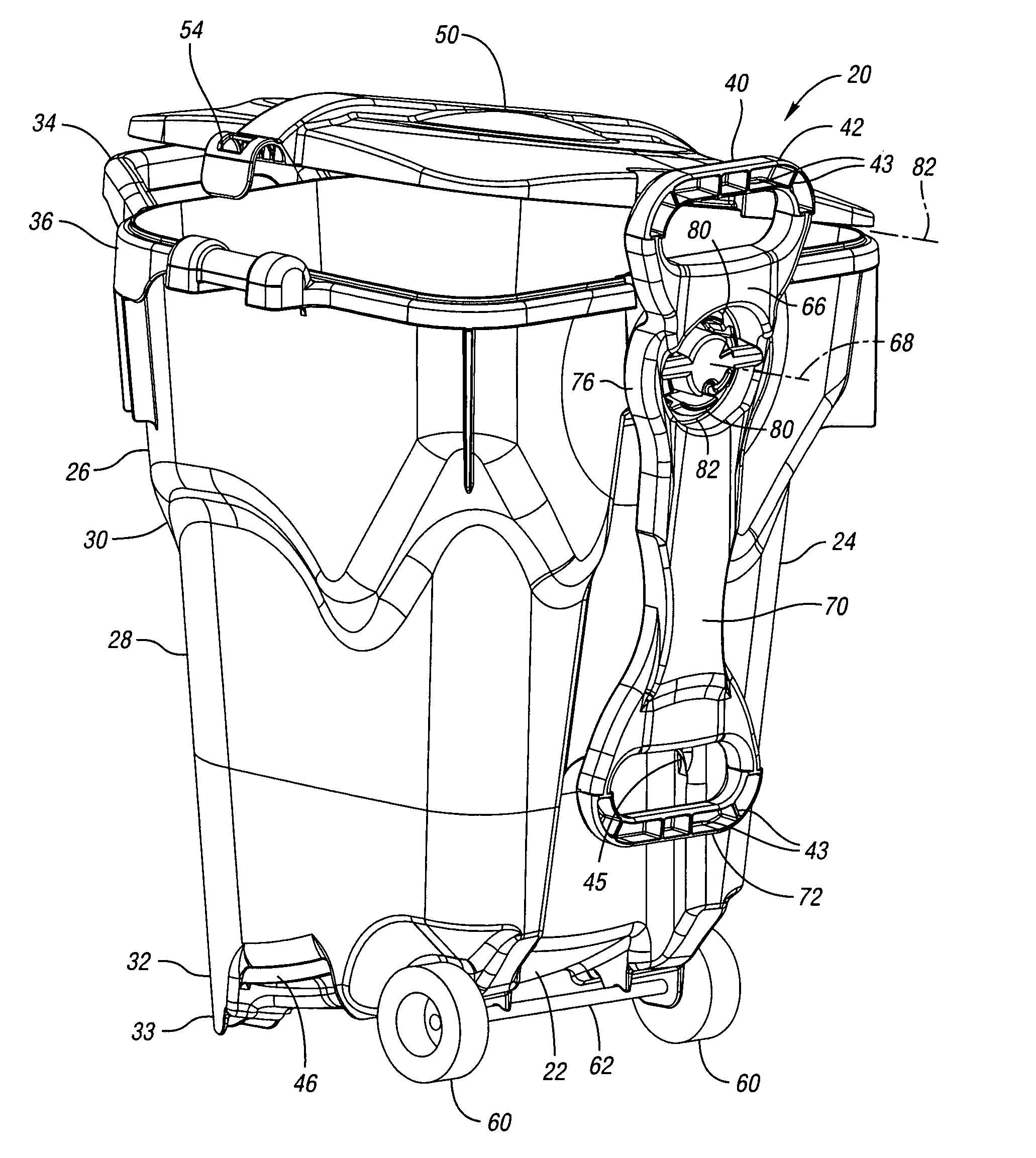
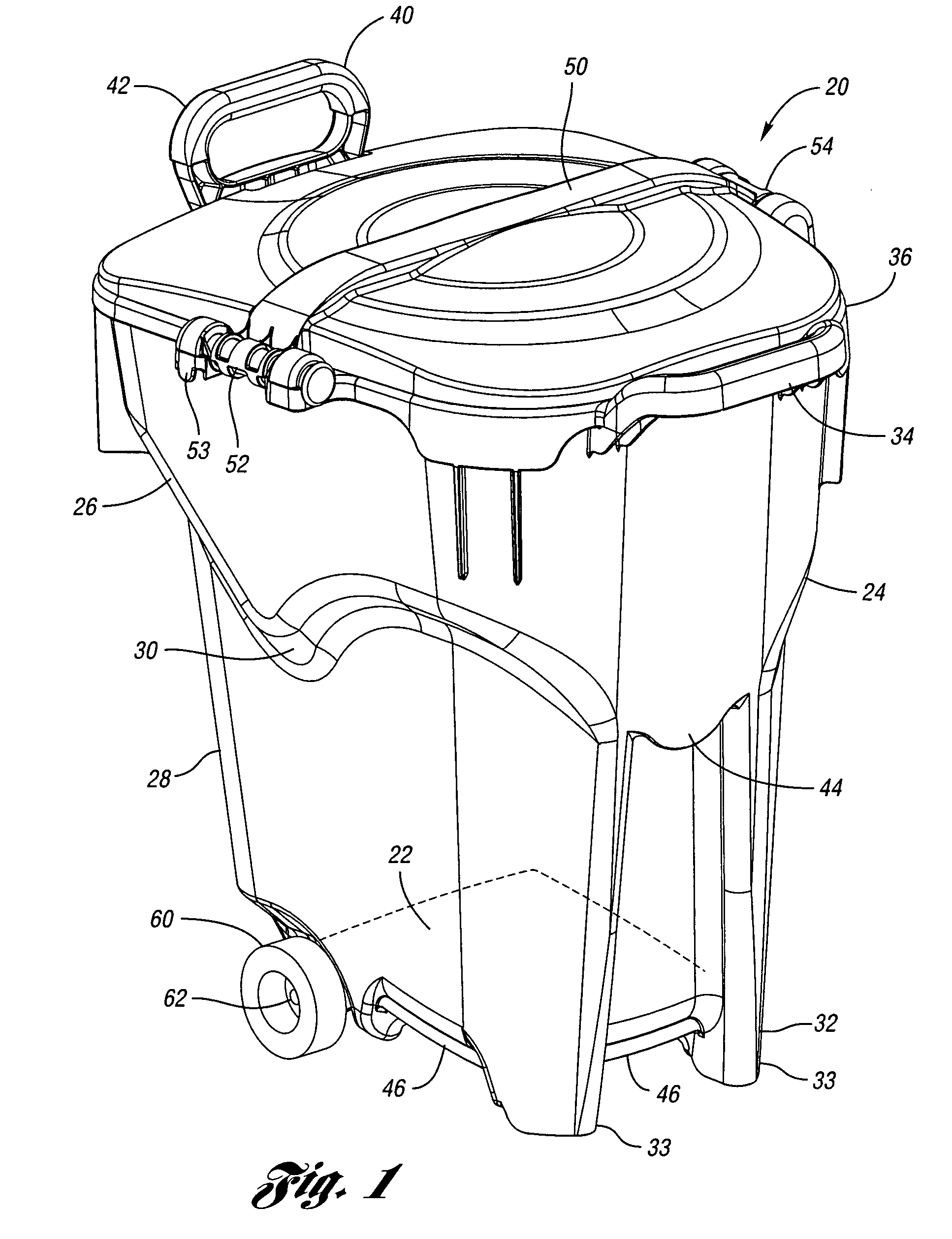
[0016]A waste container 20 according to the present invention is shown in FIG. 1. The waste container 20 includes a bottom wall 22 integrally molded with a side wall 24 that extends upwardly from the periphery of the bottom wall 22. The side wall 24 includes an upper portion 26 and a lower portion 28. The upper portion 26 has a larger diameter than the lower portion 28. A tapered mid-portion 30 of the side wall 24 connects the upper portion 26 to the lower portion 28. The tapered mid-portion 30 is contoured vertically along the side wall 24 to present an esthetically pleasing design. A base 32 extends downwardly from the bottom wall 22 beneath the side wall 24. Two feet 33 of the base 32 support the waste container 24.

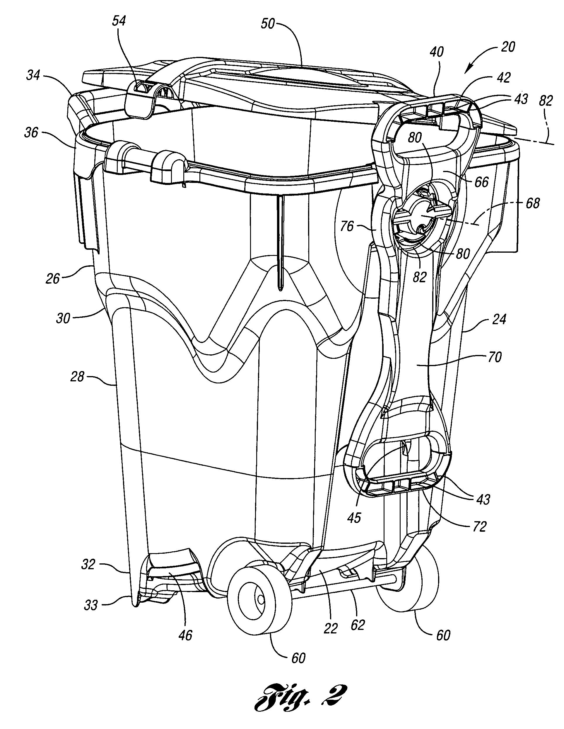
[0017]The waste container 20 includes a fixed handle 34 integrally molded with the side wall 24 and extending generally upwardly and outwardly from an upper edge 36 of the, side wall 24. The waste container 20 further includes an adjustable handle 40 opposite the fixed...


PUM


Abstract

A waste container includes a handle rotatably mounted on the side wall. The handle includes a first grip at an outer end of a short arm and a second grip at the outer end of a long arm. The handle is rotatable relative to the waste container, between a first position where the first grip extends a first distance above an upper edge of the side wall of the waste container and a second position where the second grip extends a second distance above the upper edge of the side wall, with the second distance being substantially greater than the first distance. In this manner, the handle can be moved to the proper location for either pulling the waste container on its wheels or for emptying the waste container into the hopper of a truck.

Description

BACKGROUND OF THE INVENTION[0001]The present invention relates generally to containers and, more particularly, to a waste container.[0002]Waste containers typically include a bottom wall and a side wall extending from the periphery of the bottom wall to define the container. Often, the waste container includes wheels below the side wall to facilitate the transport of a loaded waste container. Many waste containers also include handles. Some waste containers include diametrically opposed short handles, which extend slightly outwardly or slightly upwardly of the top of the side wall. While these handles are useful for lifting the waste container, such as for emptying the waste container into the hopper of a truck, these handles are not well-suited for pulling the waste container on the wheels. Longer handles are more suited to pulling the waste container on the wheels, but inconvenient for lifting the waste container.SUMMARY OF THE INVENTION[0003]The present invention provides a waste...

Claims


Application Information

Patent Timeline
Patent Type & Authority Patents(United States)
IPC IPC(8): B65D25/10B65F1/14B65F1/16
CPCB65F1/1468B65F1/16B65F1/1615B65F2001/1669B65F2220/12Y10S220/908B65F1/1473
Inventor AIKEN, CYNTHIA R.APPS, WILLIAM P.HSU, ROGER S.
Owner REHRIG PACIFIC CO INC
Learn More