
Process for modelling a 3D scene

a 3d scene and process technology, applied in the field of 3d scene modelling process, can solve the problems of large information required in defining the model or representation cost, the quality of the reconstructed model is not homogeneous, and the modelling cost is not uniform, so as to achieve the effect of reducing the cost of reconstructed models, and simplifying the depth map

Active Publication Date: 2006-09-26
MAGNOLIA LICENSING LLC
View PDF5 Cites 35 Cited by
  • Summary
  • Abstract
  • Description
  • Claims
  • Application Information

AI Technical Summary

Benefits of technology

[0024]Use of a variable threshold adapted to each pixel and calculated by an auxiliary procedure, makes it possible to control the quality of the synthetic images obtained.
[0025]The principle consists in employing a sample representative of the viewpoints which will be synthesized from the model, and in performing the construction of the model while controlling the distortion engendered in the various viewpoints of the sample. More precisely, a maximum fixed value of distortion in the images makes it possible in turn to fix at all points an upper limit on the error of approximating the 3D object by its model. The process thus allows control of the distortion error engendered in the course of rendition.
[0027]The invention allows a simplification of the depth map in such a way as to obtain a less expensive representation, while controlling the loss of quality of the reconstructed images, here the 2D geometrical distortion. The cost of the model is reduced.

Problems solved by technology

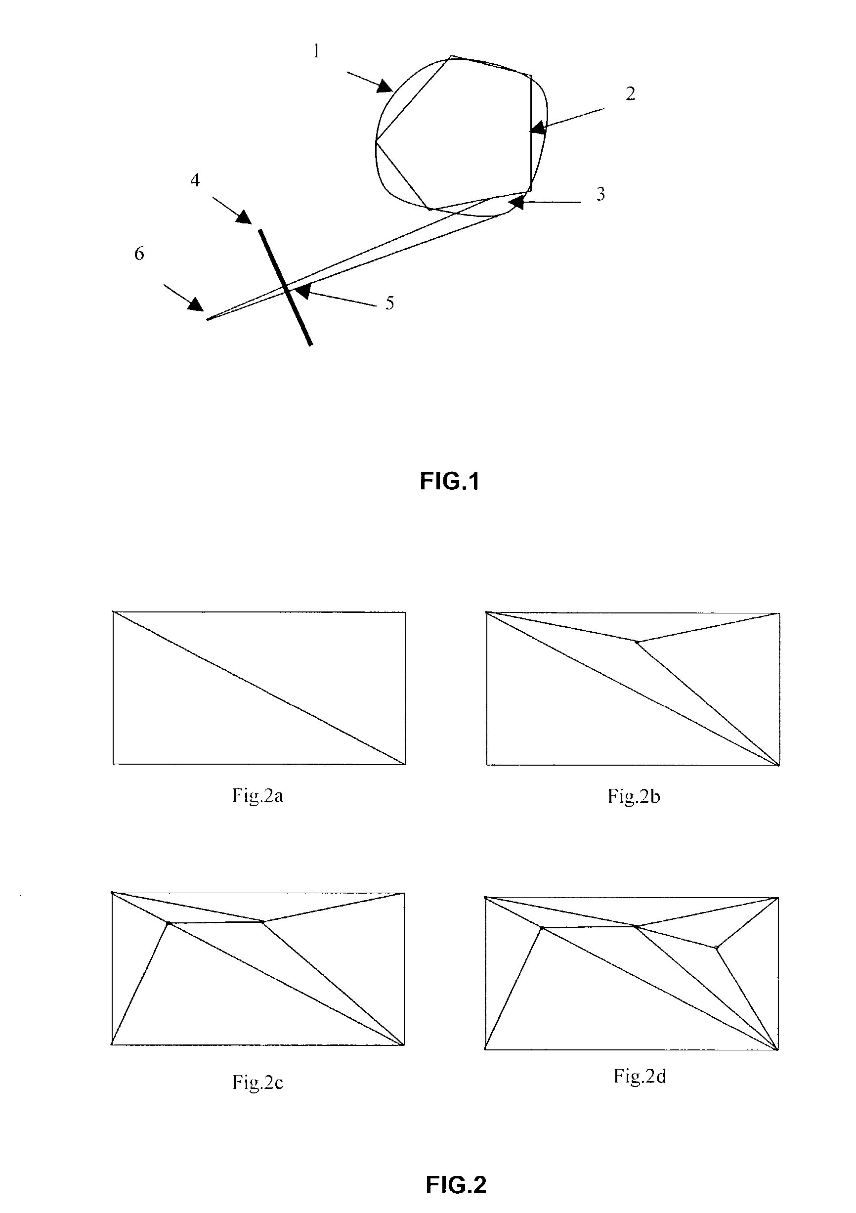
The figure shows that the error due to the approximation of the surface of a 3D object by planes may be conveyed by an error in the position of its silhouette in the image and more generally by distortion of the shape of the object and of the textures in the image.
As a result, the quality obtained is not homogeneous.
Moreover, the modelling cost, the information required in defining the model or representation cost may be considerable, for minimum required quality.

Method used


Image

  • Process for modelling a 3D scene
  • Process for modelling a 3D scene
  • Process for modelling a 3D scene

Examples


Embodiment Construction

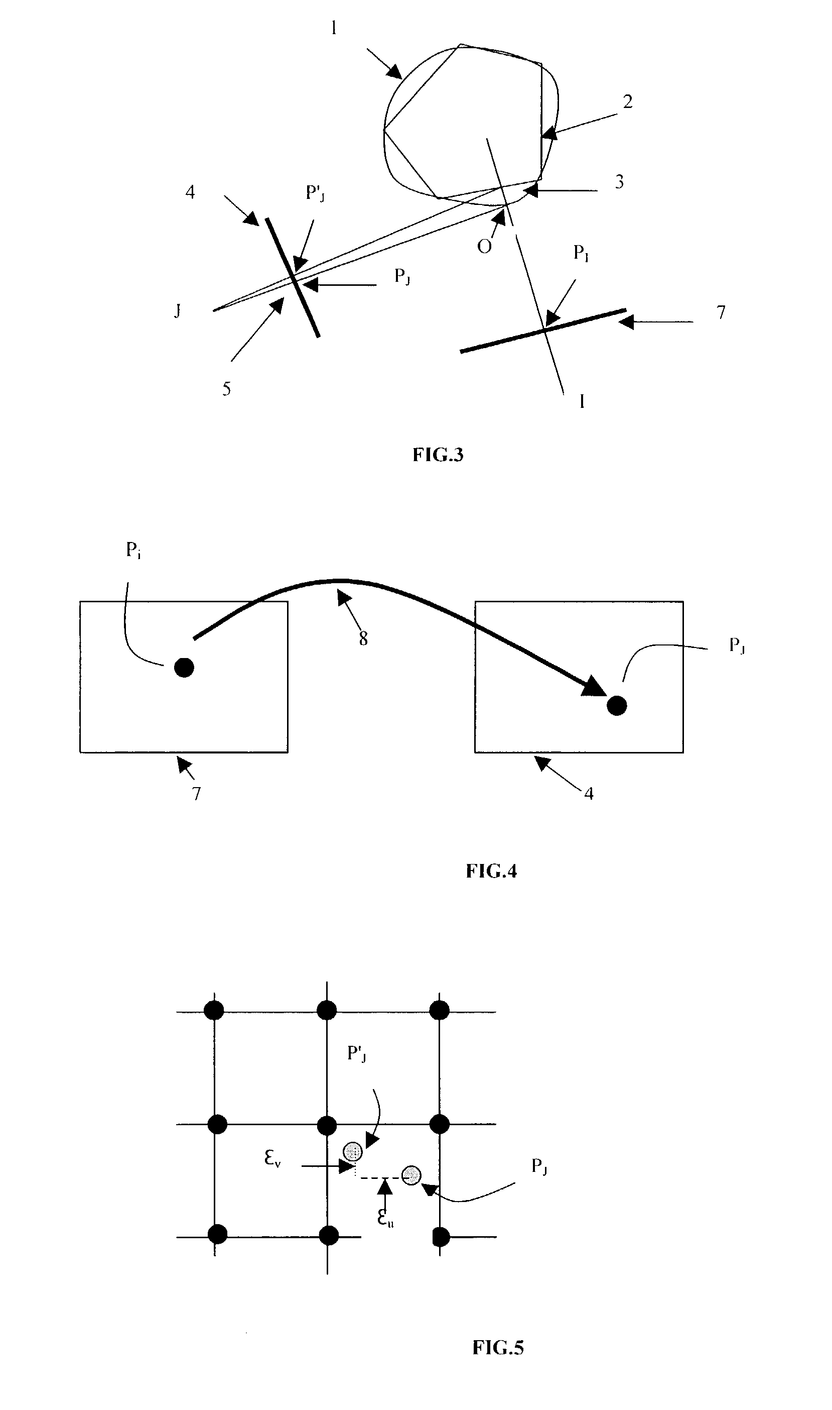
[0037]FIG. 3 represents the error in the synthesized image, resulting from the error of approximation of the surface of the 3D object, this approximation corresponding to the facetization of the depth map of the reference image, reference 7. The depth approximation error, referenced 3, is conveyed, for a lateral view from a viewpoint J, by a 2D distortion error referenced 5.

[0038]The idea is to take into account this distortion error in a 2D image for known viewpoints J or arbitrarily defined viewpoint. The quantity of these viewpoints must be sufficient to correspond to a representative sample. A maximum error is defined at the level of the 2D image which corresponds to the maximum tolerance of distortion of the image.

[0039]The objective is to model the depth map of the reference image 7 while limiting the distortion which this modelling will engender in the images for the viewpoints J. To do this, at all points of the reference image 7 we shall calculate the minimum and maximum va...


PUM


Abstract

A process for modeling a 3D scene is provided which comprises validating the model by determining a maximum permitted distortion (5) on a 2D synthesized image (4), generated by the approximation inherent in the model (2); calculating for a point I of a reference image (7) and on a set of synthesized images (4) representing the 3D point of the scene corresponding to this point I, of the minimum (zi−Δzi1) and maximum (zi+Δzi2) depth values of the depth zi of this point I corresponding to this maximum distortion, calculating a span around the depth zi of this point I, dependant on the minimum value of the error Δzi2 and on the minimum value of the error Δzi1 among the values calculated for the synthesized images of the set.

Description

FIELD OF THE INVENTION[0001]The invention relates to a 3D scene modelling process and in particular to a process for modelling or for approximating a 3D object by a plane faceted 3D model allowing control of distortion in the synthesized images.BACKGROUND OF THE INVENTION[0002]The invention entails the construction of a 3D model of a scene on the basis of a reference image possessing a depth map.[0003]FIG. 1 represents the surface of an object in 3D space referenced 1. An approximation of this object by facetization or triangulation yields a model whose surface is referenced 2. A synthesized image is obtained by projecting the model onto a plane 4 from a viewpoint 6. The error 3 due to the approximation of the surface of the object to that of the model is conveyed on the image by a 2D distortion referenced 5. The figure shows that the error due to the approximation of the surface of a 3D object by planes may be conveyed by an error in the position of its silhouette in the image and ...

Claims


Application Information

Patent Timeline
Patent Type & Authority Patents(United States)
IPC IPC(8): G06K9/00G06T15/00G06T17/20H04N13/02
CPCG06T17/20G06T17/00
Inventor ROBERT, PHILIPPENICOLAS, YANNICK
Owner MAGNOLIA LICENSING LLC
Learn More