
Method and device for degassing a suspension, specifically a fiber stock suspension

Inactive Publication Date: 2006-09-05
VOITH PATENT GMBH
View PDF30 Cites 1 Cited by
  • Summary
  • Abstract
  • Description
  • Claims
  • Application Information

AI Technical Summary

Benefits of technology

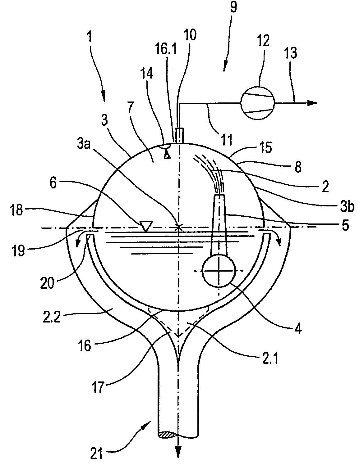
[0020]An advantage of the present invention is that the device for producing the vacuum in the tank includes one vacuum connection, one vacuum line and at least one vacuum pump with a line located in the upper interior of the tank. Alternatively several vacuum connections can, at any given time, be operated individually with a separate vacuum line and a separate vacuum pump for each line, or with individual vacuum lines and a common vacuum pump with a line connected thereto.
[0021]A further advantageous embodiment of the present invention includes several nozzles located in the upper interior tank area, for moistening the interior surface of the tank that does not come into contact with the suspension. This arrangement positively influences the speed and efficiency of the suspension de-gassing process taking place in the tank. The moistening also prevents fiber, fines or ash deposits.
[0022]It is also advantageous, according to the present invention, if the distributor pipe is positioned parallel or approximately parallel to the tank axis. The distributor pipe can be located either outside or inside the tank. This arrangement results in special advantages and technological advantages in the form of distribution uniformity.
[0023]In accordance with a method of the present invention the separated excess suspension is discharged sideways through an overflow that is located in the tank outside wall, that is positioned preferably parallel to the tank axis, and having an overflow edge. This provides the opportunity to locate the overflow definitively in a fluidic optimum position between the supply of suspension and discharge of the gas-free suspension, allowing further improvement of the hydraulics, and additionally lowering equipment costs.
[0024]It is understood that the aforementioned characteristics of the invention that are subsequently further explained, may be utilized not only in the cited combinations, but also in other combinations, or self-contained, without abandoning the scope of the invention.

Problems solved by technology

Even though this device permits flexibility with regard to the position and form of the overflow, it does not however permit fluidic optimum positioning of the overflow.

Method used


Image

  • Method and device for degassing a suspension, specifically a fiber stock suspension
  • Method and device for degassing a suspension, specifically a fiber stock suspension
  • Method and device for degassing a suspension, specifically a fiber stock suspension

Examples


Embodiment Construction

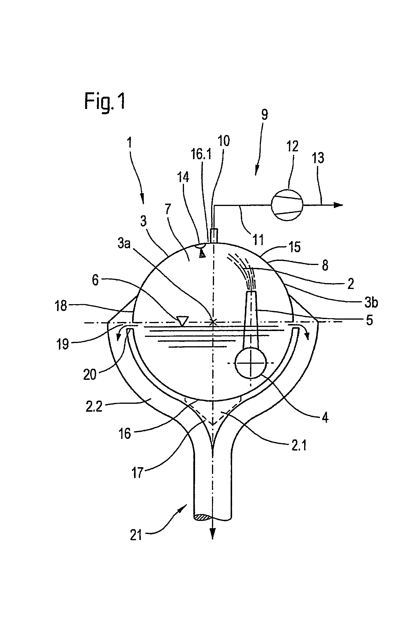
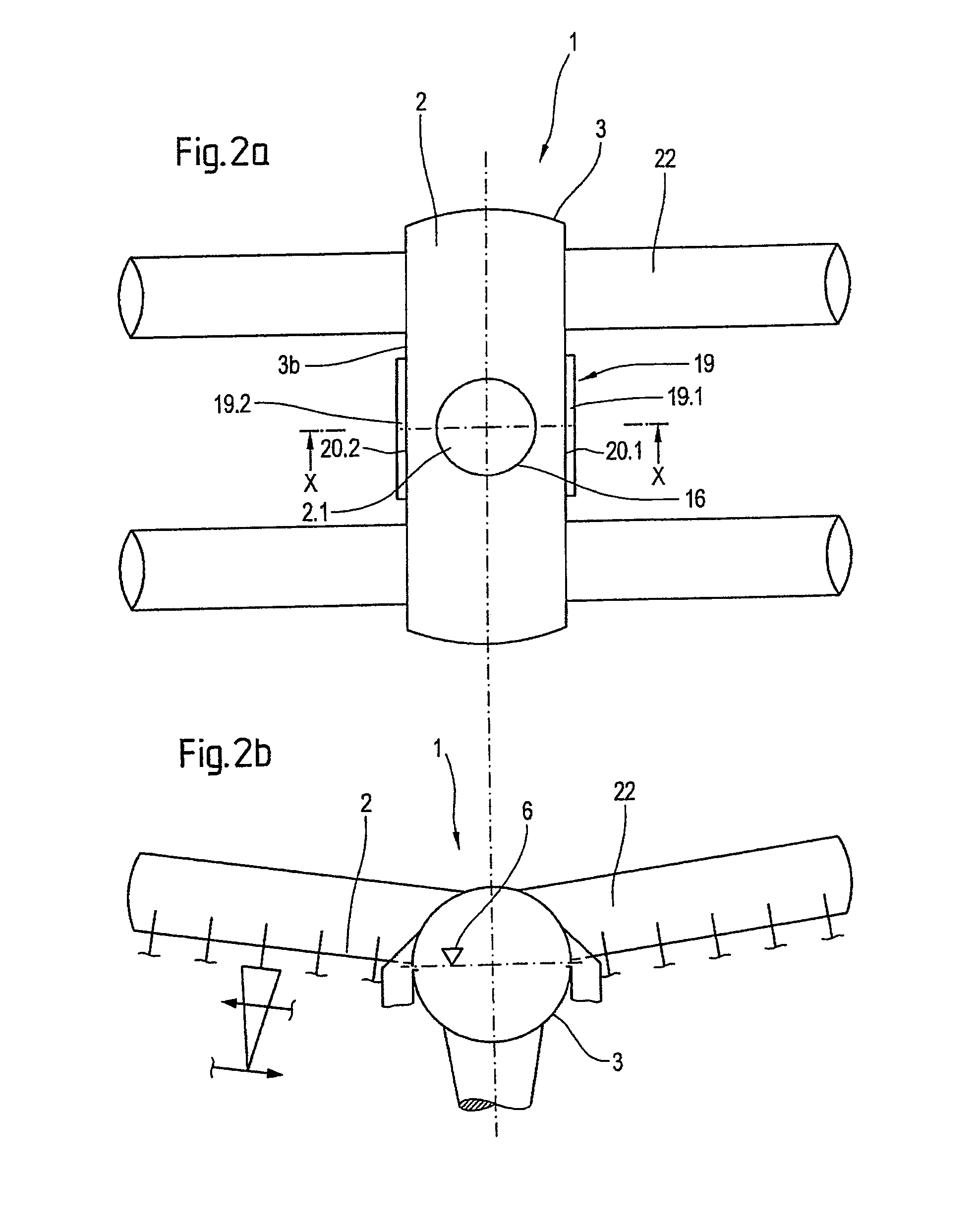
[0038]Referring now to the drawings, and, more particularly to FIG. 1, there is shown a device 1 for degassing a suspension 2, including horizontally stretched out tank 3 with a tank axis 3a and a tank outside wall 3b. Suspension 2 is fed in the form of a thin mixture through at least one distributor pipe 4 that is positioned parallel to tank axis 3a and from which a multitude of successive jet tubes 5 originate for the purpose of feeding suspension 2 into tank 3. To improve the degassing capabilities of device 1, suspension 2, that at this point still contains gas, is supplied through jet tubes 5 into tank 3, above liquid level 6, whereby gas 7 that may be present in the form of bubbles in suspension 2 is separated before added suspension 2 comes into contact with suspension 2 already present in tank 3. Jet tubes 5 terminate prior to tank ceiling 8, thereby reinforcing the degassing process of suspension 2 since suspension 2 impacts tank ceiling 8.

[0039]Now, additionally referring ...


PUM

PropertyMeasurementUnit
Lengthaaaaaaaaaa
Lengthaaaaaaaaaa
Lengthaaaaaaaaaa

Abstract

The invention relates to a method and a device for degassing of suspension, specifically fiber stock suspension. The method according to the invention is characterized in that separated excess suspension is discharged sideways through an overflow having an overflow edge that is located in the tank outside wall and is positioned parallel to the tank axis. The device according to the invention is characterized in that the overflow includes at least one overflow having an overflow edge that is located in the tank outside wall and is positioned parallel to the tank axis and that at least one overflow system, for the purpose of discharging the separated excess suspension, is located following the overflow.

Description

BACKGROUND OF THE INVENTION[0001]1. Field of the Invention[0002]The invention relates to a device and method for degassing a suspension, and, more particularly, to a method and device for degassing a fiber suspension.[0003]2. Description of the Related Art[0004]In a broad sense the term “suspension” refers to white water containing the essential components of fines and ash, or clarified water containing a minimum of fines and ash content.[0005]Methods and devices for degassing suspensions, specifically fiber stock suspensions that are utilized in paper and cardboard production, are well known to the experts in this field. Consistent with their names, the devices are intended to degas suspensions. During the degassing process other light contaminates, which would otherwise interfere with the paper or cardboard production, are removed by the devices. The devices consist of large tanks into which the suspension that is to be supplied to the paper or cardboard machine, is fed in the for...

Claims


Application Information

Patent Timeline
IPC IPC(8): B01D19/00D21D5/26
CPCD21D5/26B01D19/0047
Inventor BEUERMANN, KARL-HEINZ
Owner VOITH PATENT GMBH
Learn More