
Load assist mechanism for an overhead bin

Inactive Publication Date: 2006-08-15
HEATH TECNA
View PDF16 Cites 45 Cited by
  • Summary
  • Abstract
  • Description
  • Claims
  • Application Information

AI Technical Summary

Problems solved by technology

Although overhead stowage bins are effective at stowing items, such as luggage, they are not without their problems.
As an example, a loaded overhead luggage bin of an aircraft may be difficult to push upward into the stowed position due to the weight of the luggage within the bin.

Method used


Image

  • Load assist mechanism for an overhead bin
  • Load assist mechanism for an overhead bin
  • Load assist mechanism for an overhead bin

Examples


Embodiment Construction

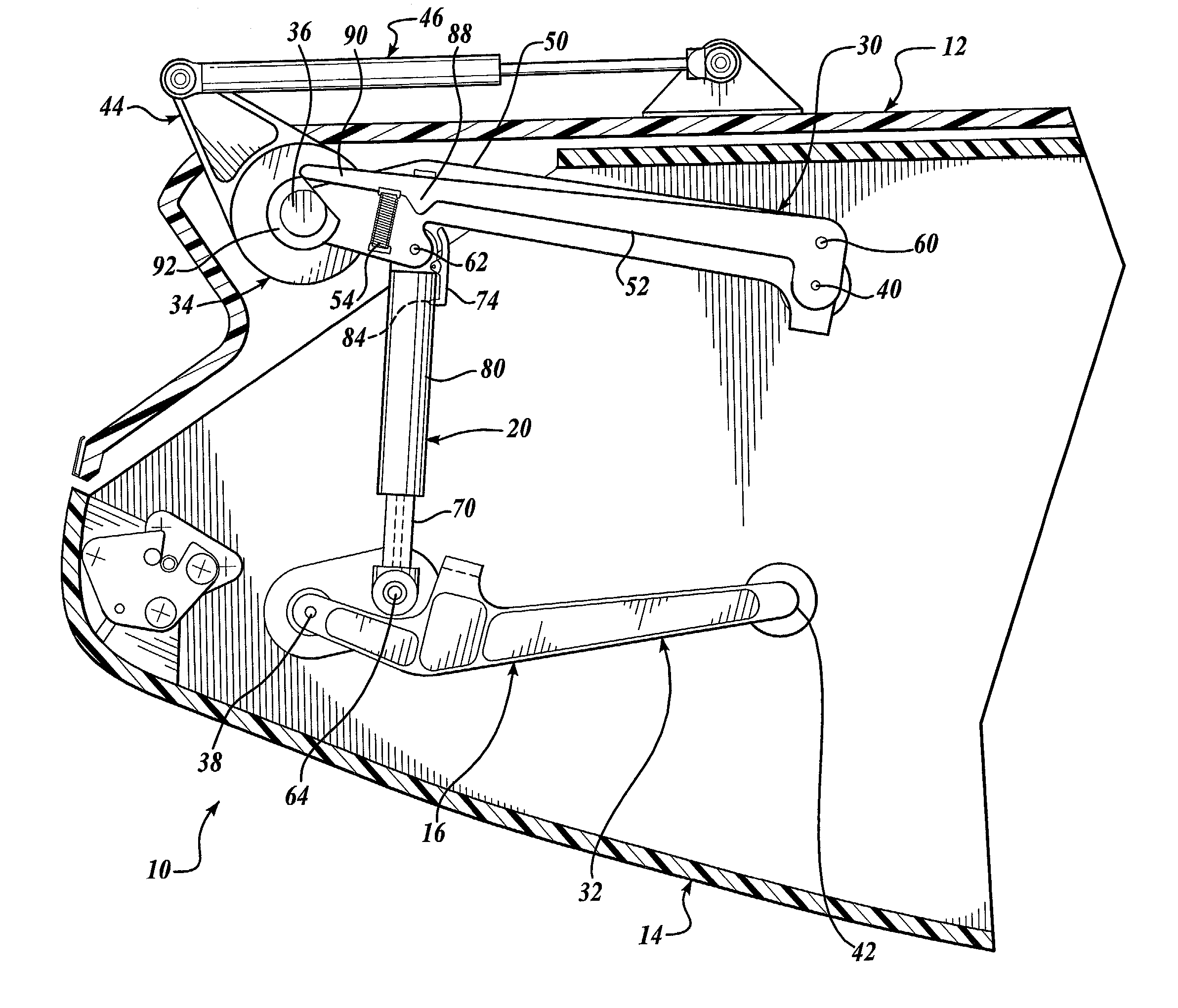
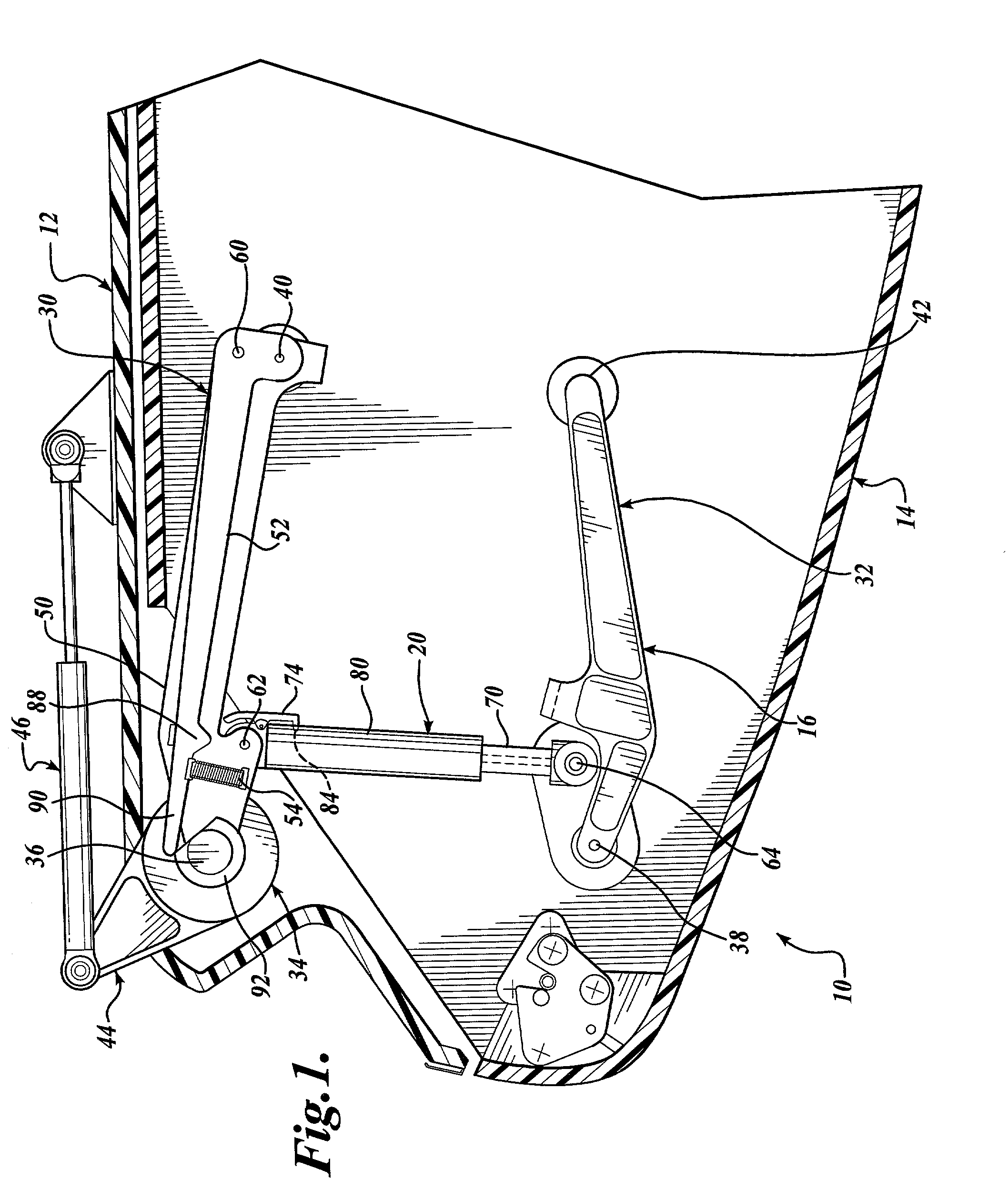
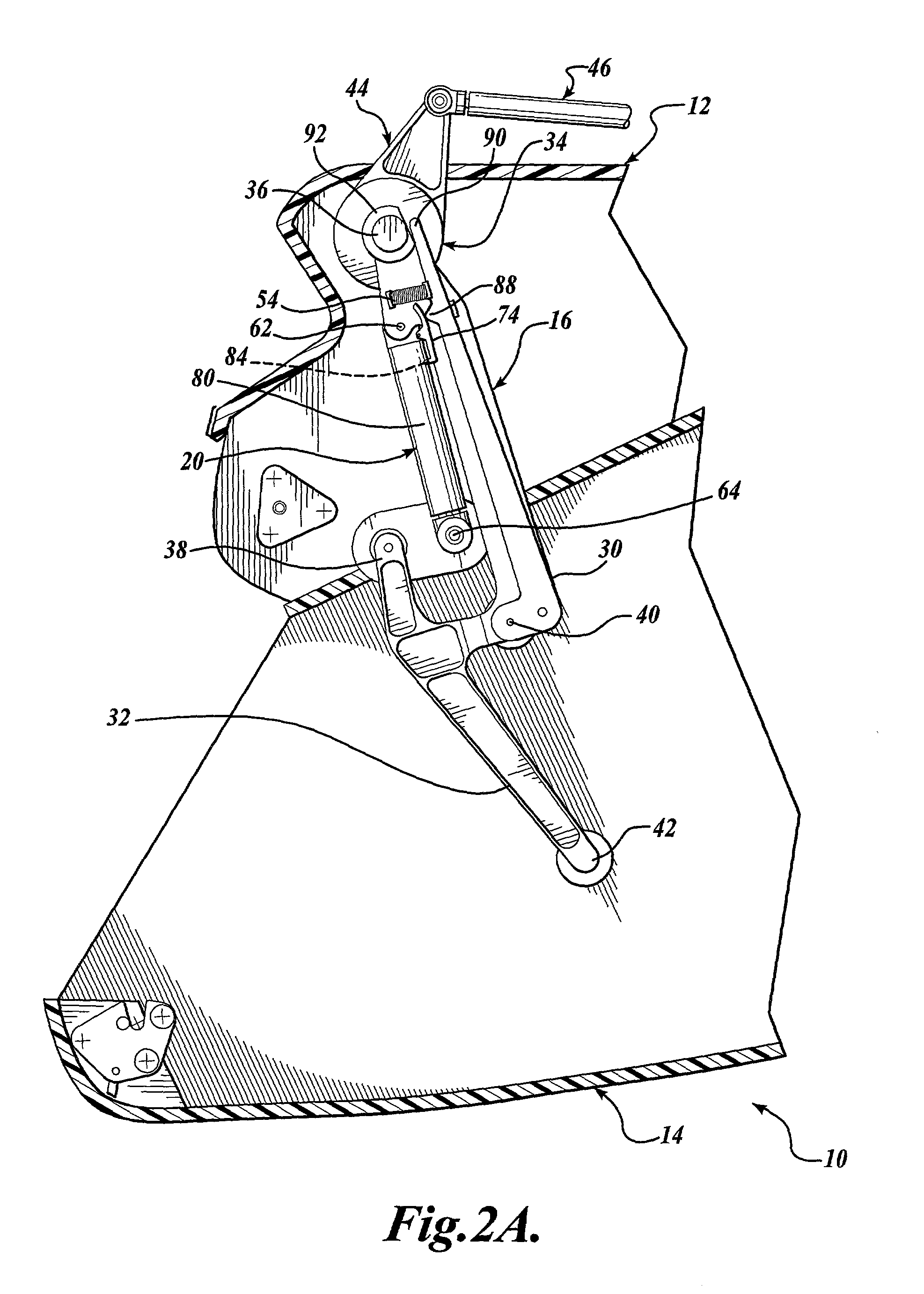
[0022]FIGS. 1–2B illustrate a pull-down stowage bin assembly 10 (hereinafter “bin assembly 10”) constructed in accordance with one embodiment of the present invention. The bin assembly 10 includes a housing 12, a bucket assembly 14, linkage assembly 16, and actuator 20. The bucket assembly 14 is connected to the housing 12 by the linkage assembly 16. Although a single linkage assembly 16 is illustrated, it should be apparent that a second, similarly configured linkage assembly (not shown) may be disposed at an opposite end of the bucket assembly 14 to control the operational movement of the bucket assembly 14. Further, either one or both linkage assemblies includes an actuator 20, which is pivotally connected to the upper arm assembly 30 by a pivot pin 62 and the housing 12 by a pivot pin 64. For ease of description, only one linkage assembly will be described in greater detail.

[0023]The linkage assembly 16 includes an upper and lower arm assembly 30 and 32. The upper and lower arm ...


PUM


Abstract

A luggage bin assembly (10) adapted to be disposed within a vehicle is provided. The luggage bin assembly includes a bin (14) reciprocally mounted for movement between an opened position and a closed position. The luggage bin assembly also includes a linkage assembly (16) adapted to be hingedly mounted to the bin for swinging movement with the bin as the bin is reciprocated between the open and closed positions. A reciprocating assist mechanism (20) is coupled to the linkage mechanism to selectively apply an assist load to the linkage assembly when the bin is reciprocated between the opened and closed position.

Description

CROSS-REFERENCES TO RELATED APPLICATIONS[0001]In accordance with 35 U.S.C. § 119(e), this application claims the benefit of U.S. Provisional Patent Application Ser. No. 60 / 293,348, filed May 24, 2001, and U.S. Provisional Patent Application Ser. No. 60 / 293,599, filed May 25, 2001, the disclosures of which are both hereby expressly incorporated by reference.FIELD OF THE INVENTION[0002]This invention relates generally to actuators for vehicle stowage bins and, more particularly, to spring assist actuators.BACKGROUND OF THE INVENTION[0003]Pull-down bucket stowage bins are commonly used to stow luggage in vehicles having a passenger compartment, such as buses and commercial aircraft. Typically, such stowage bins are reciprocally mounted to or near the ceiling of the passenger compartment, such that they are located above rows of passenger seats within the vehicle. As mounted, the bins may be reciprocated between an open position, where items may be placed within the bin, and a closed po...

Claims


Application Information

Patent Timeline
IPC IPC(8): A47F5/08B64D11/00
CPCB64D11/003
Inventor BURROWS, RALPHFRAZIER, JOE
Owner HEATH TECNA
Learn More