Combined oil ring
a technology of oil ring and oil ring, which is applied in the direction of brake systems, machines/engines, transportation and packaging, etc., can solve the problems of increased friction, increased contact pressure, increased friction, etc., and achieves the effect of reducing friction, reducing friction, and reducing friction
- Summary
- Abstract
- Description
- Claims
- Application Information
AI Technical Summary
Benefits of technology
Problems solved by technology
Method used
Image

Examples
first embodiment
[0050]The preferred first embodiment of the present invention is described next while referring to the accompanying drawings.
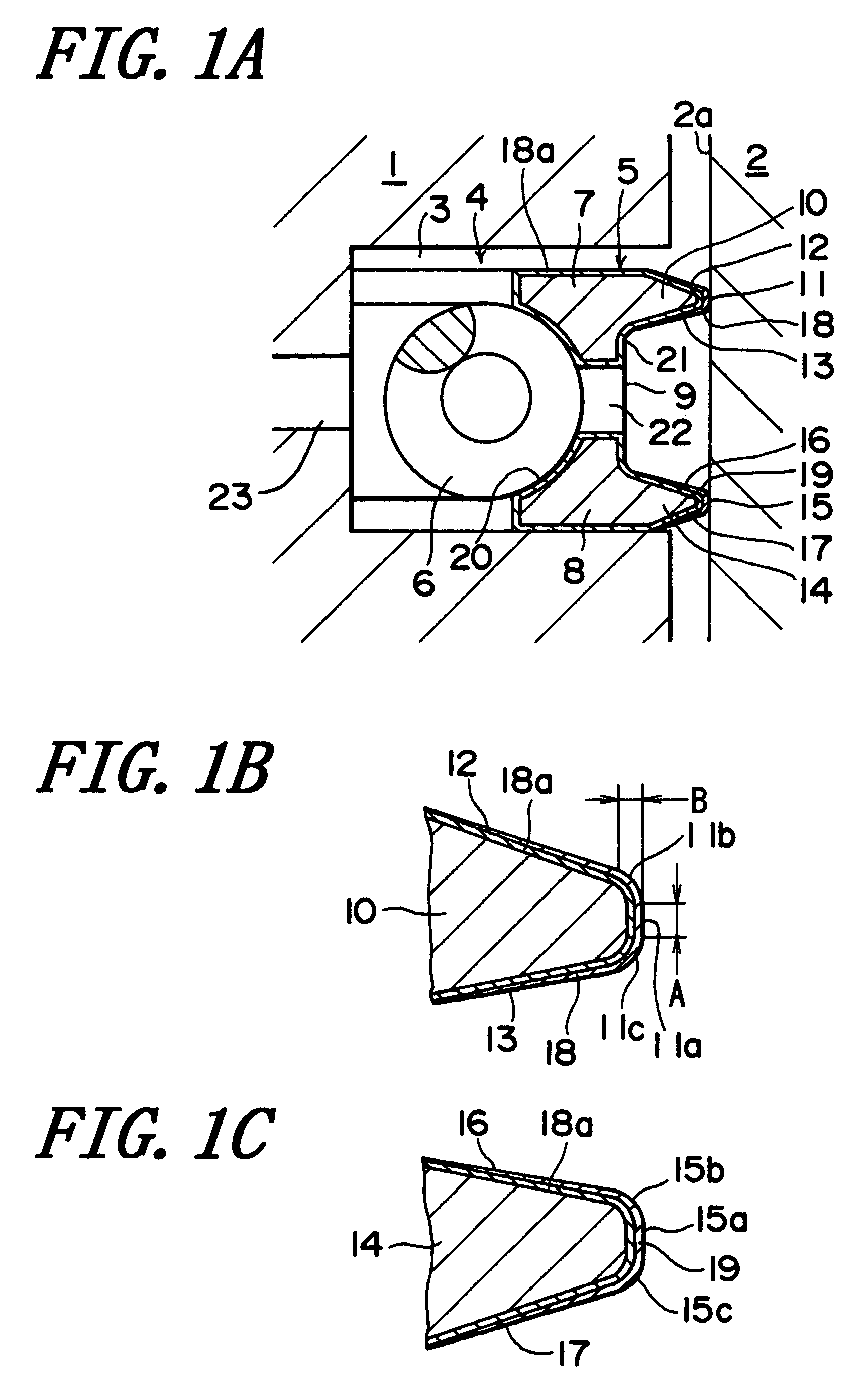
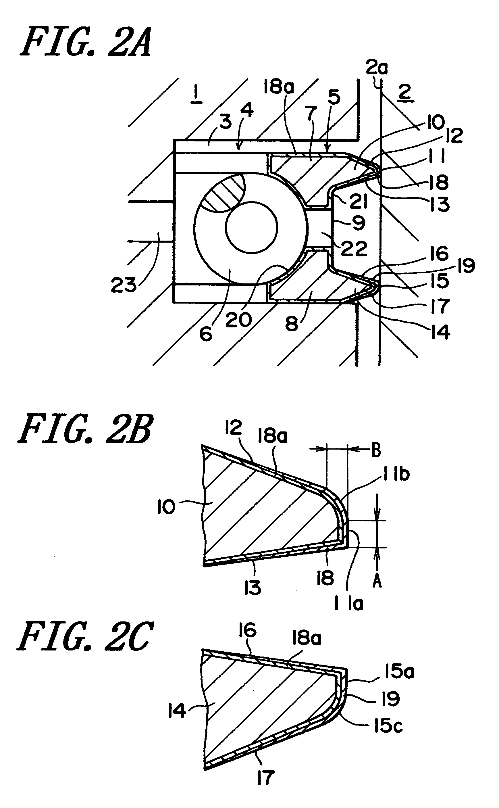
[0051]In FIG. 1, the reference numeral 1 denotes a piston, and the reference numeral 2 denotes a cylinder. A combined oil ring 4 is installed in a ring groove 3 formed on the outer circumference of the piston 1. The combined oil ring 4 is a two-piece type combined oil ring made of steel. The combined oil ring 4 is comprised of an oil ring 5 and a coil expander 6.
[0052]The oil ring 5 is a steel ring with a generally I-shaped cross section and has a gap. The oil ring 5 is comprised of a pair of upper and lower rails 7 and 8 extending to the periphery and a straight web 9 extending to the periphery and connecting the upper and lower rails 7 and 8.
[0053]A protrusion 10 on the outer circumferential side of the upper rail 7 is formed in a cross section with a roughly trapezoidal shape defined by an outer circumferential surface 11 and a pair of oblique upper and low...
second embodiment
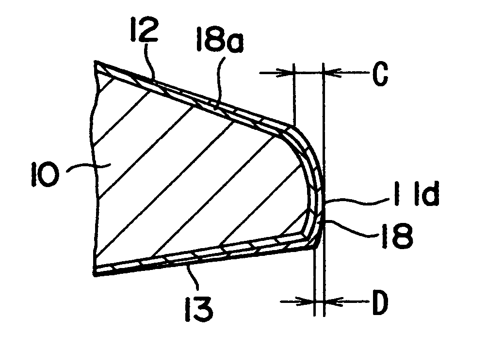
[0060]In the second embodiment, the outer circumferential surface 11 of the upper rail 7 of the oil ring 5 is comprised of a flat surface 11a for sliding on the cylinder inner circumferential surface 2a, and an arc-shaped curved surface 11b smoothly joining to the upper end of the flat surface 11a and to the upper surface 12 of the upper rail 7. The axial width A of the flat surface 11a is from 0.05 to 0.3 millimeters. The radial width B of the arc-shaped curved surface 11b is from 25 to 75 micrometers.
[0061]The outer circumferential surface 15 of the lower rail 8 is comprised of a flat surface 15a for sliding on the cylinder inner circumferential surface 2a, and an arc-shaped curved surface 15c smoothly joining to the lower end of the flat surface 15a and to the lower surface 17 of the lower rail 8. The axial width of the flat surface 15a is from 0.05 to 0.3 millimeters. The radial width of the arc-shaped curved surface 15c is from 25 to 75 micrometers.
[0062]In the case of the seco...
third embodiment
[0064]In the third embodiment, the outer circumferential surface 11 of the upper rail 7 of the oil ring 5 is comprised of an arc-shaped curved surface 11b smoothly joining to the upper surface 12 of the upper rail 7 with the radial rail width decreasing from the lower end of the upper rail 7. The radial width B of the arc-shaped curved surface 11b is from 25 to 75 micrometers.
[0065]The outer circumferential surface 15 of the lower rail 8 is comprised of an arc-shaped curved surface 15c smoothly joining to the lower surface 17 of the lower rail 8 with the radial rail width decreasing from the upper end of the lower rail 8. The radial width of the arc-shaped curved surface 15c is from 25 to 75 micrometers.
[0066]In the case of this third embodiment also, even if a tilt in the piston 1 occurs, an increase in localized friction due to the rail outer circumferential corner is suppressed and low friction is achieved. The sharp corner on the lower end of the upper rail 7 contributes to impr...
PUM
 Abstract
Description
Claims
Application Information
 - R&D
- Intellectual Property
- Life Sciences
- Materials
- Tech Scout
- Unparalleled Data Quality
- Higher Quality Content
- 60% Fewer Hallucinations
Browse by: Latest US Patents, China's latest patents, Technical Efficacy Thesaurus, Application Domain, Technology Topic, Popular Technical Reports.
© 2025 PatSnap. All rights reserved.Legal|Privacy policy|Modern Slavery Act Transparency Statement|Sitemap|About US| Contact US: help@patsnap.com