
Ventilated clutch assembly with reduced-slip sheave surfaces

a clutch assembly and sheave surface technology, applied in the direction of belt/chain/gearing, gear lubrication/cooling, gear elements, etc., can solve the problems of v-belt breaking down, v-belt being torn or shredded, v-belt breaking down and having to be replaced, etc., to achieve the effect of reducing belt slippag

Inactive Publication Date: 2006-07-04
POLARIS IND INC
View PDF28 Cites 18 Cited by
  • Summary
  • Abstract
  • Description
  • Claims
  • Application Information

AI Technical Summary

Benefits of technology

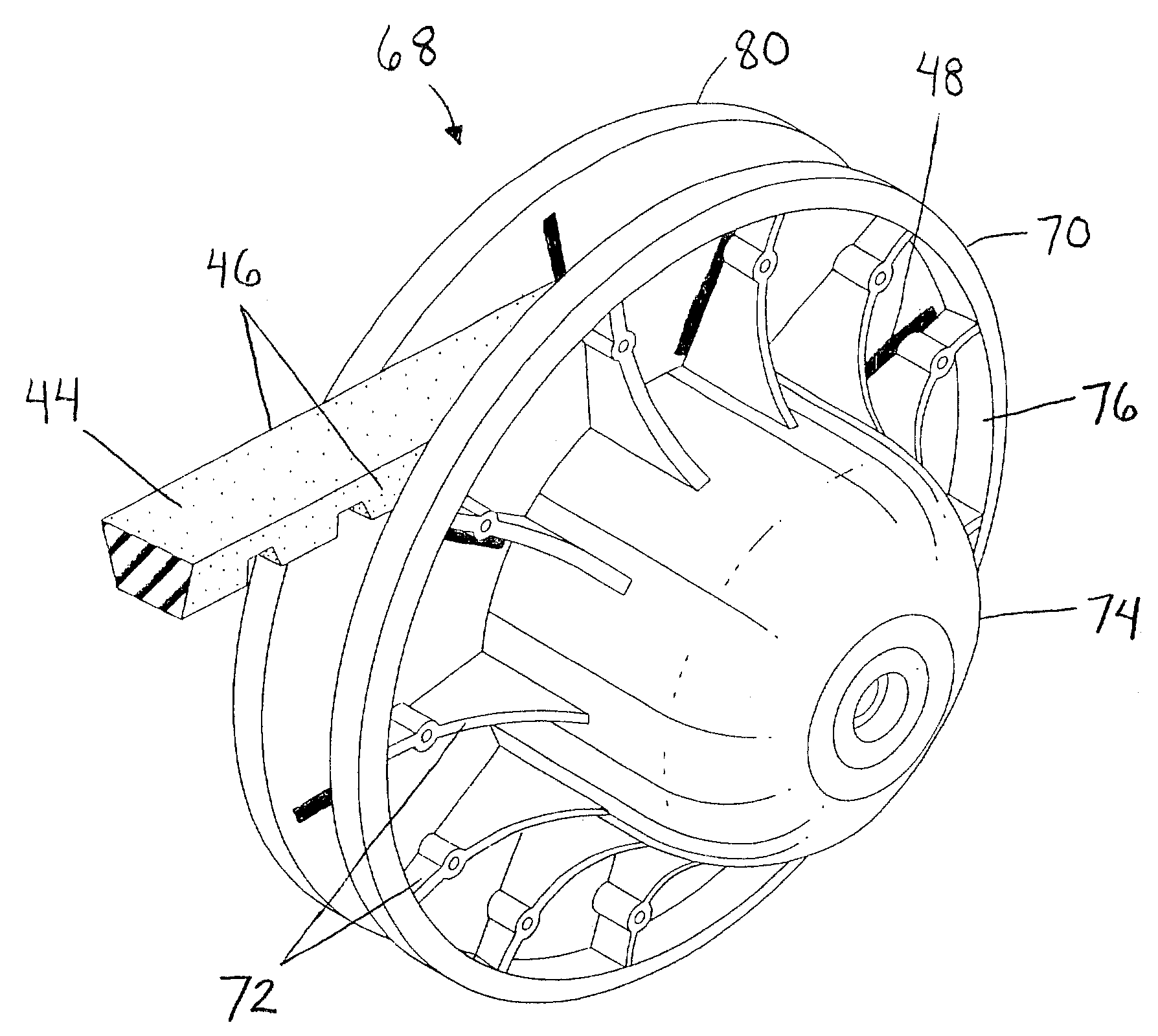
[0005]The invention provides an apparatus and method for cooling a V-belt in a clutch assembly of a CVT. As previously mentioned, the CVT is comprised of a drive clutch assembly, a driven clutch assembly, and an endless V-belt disposed about the drive and driven clutch assemblies. The invention will cool the V-belt as it rides about the drive clutch and driven clutch assemblies. In addition, the invention provides a method for providing a reduced-slip sheave surface for the V-belt in a clutch assembly of a CVT. Normally, as the V-belt rides about the drive and driven clutch assemblies, the V-belt contacts inner surfaces of the clutch assemblies. The invention will reduce belt slippage across the inner surfaces of the clutch assemblies.

Problems solved by technology

However, this mechanism is also disadvantageous because, by its very function, the mechanism produces external stress to a V-belt that is utilized within the CVT.
This external stress eventually causes the V-belt to break down, with the V-belt being torn apart or shredded.
As previously mentioned, while the operation of the CVT allows the rider to not be concerned with shifting gears, it also promotes external stress to the V-belt, eventually resulting in the V-belt breaking down and having to be replaced.
While this is a well-known occurrence, it is also a general inconvenience for the rider, since he subsequently has to spend time and money buying and replacing the belt.

Method used


Image

  • Ventilated clutch assembly with reduced-slip sheave surfaces
  • Ventilated clutch assembly with reduced-slip sheave surfaces
  • Ventilated clutch assembly with reduced-slip sheave surfaces

Examples


Embodiment Construction

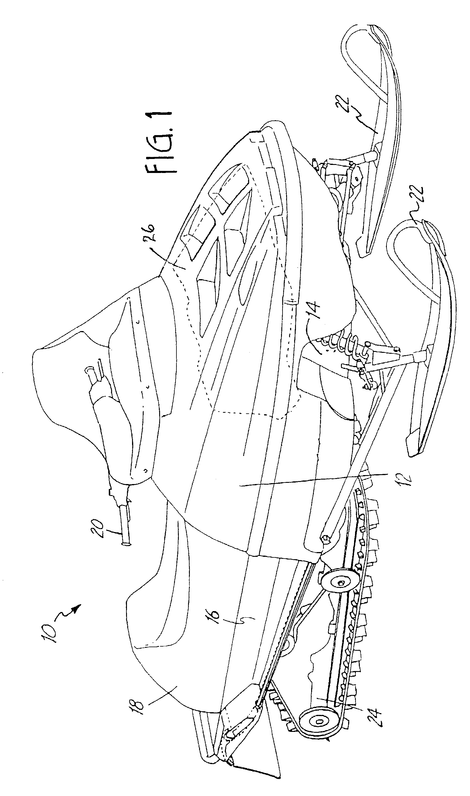
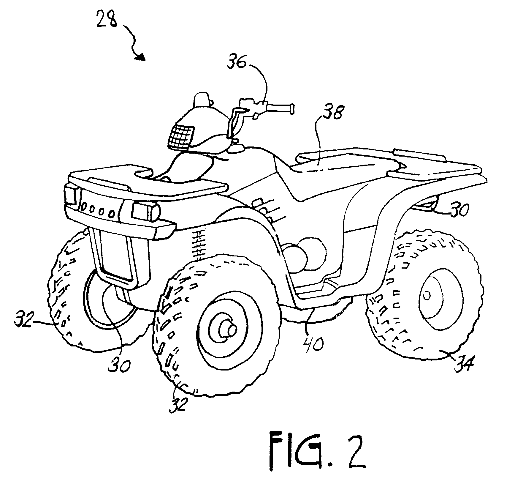
[0016]The following detailed description is to be read with reference to the drawings, in which like elements in different figures have like reference numerals. The drawings, which are not necessarily to scale, depict selected embodiments, but are not intended to limit the scope of the invention. It will be understood that many of the specific details of the vehicle incorporating the system illustrated in the drawings could be changed or modified by one of ordinary skill in the art without departing significantly from the spirit of the invention. The function and operation of continuously variable transmissions (CVTs) are well known (see e.g., U.S. Pat. No. 3,861,229, Domaas, the teachings of which are incorporated herein by reference) and need not be described in detail. The CVT of the invention is designed for use on vehicles such as snowmobiles and ATVs, however it may be used on such other vehicles as golf carts and the like.

[0017]A snowmobile 10 having a system in accordance wi...


PUM


Abstract

The invention provides an apparatus and method for cooling a V-belt in a clutch assembly of a CVT. As previously mentioned, the CVT is comprised of a drive clutch assembly, a driven clutch assembly, and an endless V-belt disposed about the drive and driven clutch assemblies. The invention will cool the V-belt as it rides about the drive clutch and driven clutch assemblies. In addition, the invention provides a method for providing a reduced-slip sheave surface for the V-belt in a clutch assembly of a CVT. Normally, as the V-belt rides about the drive and driven clutch assemblies, the V-belt contacts inner surfaces of the clutch assemblies. The invention will reduce belt slippage across the inner surfaces of the clutch assemblies.

Description

TECHNICAL FIELD[0001]The invention relates to continuously variable transmissions, such as those used in snowmobiles, and, in particular, to the drive and driven clutch assemblies that function thereon.BACKGROUND OF THE INVENTION[0002]Split sheave continuously variable transmissions (CVTs) are used in a variety of recreational type off-road vehicles such as snowmobiles, all-terrain vehicles (ATVs), golf carts, and the like. CVTs, as their name implies, do not require shifting through a series of forward gears, but rather provide a continuously variable gear ratio that automatically adjusts as the vehicle speeds up or slows down, thus providing relatively easy operation for a rider. This automatic adjustment mechanism is advantageous to the rider because he needs not be bothered by shifting gears for increasing or decreasing vehicle speed. However, this mechanism is also disadvantageous because, by its very function, the mechanism produces external stress to a V-belt that is utilized...

Claims


Application Information

Patent Timeline
IPC IPC(8): F16H57/04
CPCF16H55/56F16H57/0489F16H57/0415
Inventor SAAGGE, DARIN
Owner POLARIS IND INC
Learn More