Valve control device for an internal combustion engine and internal combustion engine comprising such a device

Active Publication Date: 2006-07-04
PEZHO SITROEN AUTOMOBILS SA
View PDF8 Cites 2 Cited by
  • Summary
  • Abstract
  • Description
  • Claims
  • Application Information

AI Technical Summary

Benefits of technology

[0024]For example, the deceleration of a vehicle from a high speed by the driver removing his foot from the gas pedal reduces the load to the minimum that can be reached as a function of the speed until a return to the idling engine speed.
[0036]According to one embodiment, the magnet, located on an electromagnet of the actuator, ensures that the valve is maintained in an open or closed position without requiring a holding current.

Problems solved by technology

However, the use of a magnet 118 (FIG. 1b) has the drawback that when the plate 114 must move away from an electromagnet 108 equipped with the magnet 118 to control a switching of the valve 110, the magnetic field Hai generated by that magnet exerts a restoring force, which opposes this moving away, which interferes with the control of the valve 110, slowing down its displacement and completely preventing its transition.

Method used


Image

  • Valve control device for an internal combustion engine and internal combustion engine comprising such a device
  • Valve control device for an internal combustion engine and internal combustion engine comprising such a device
  • Valve control device for an internal combustion engine and internal combustion engine comprising such a device

Examples


Embodiment Construction

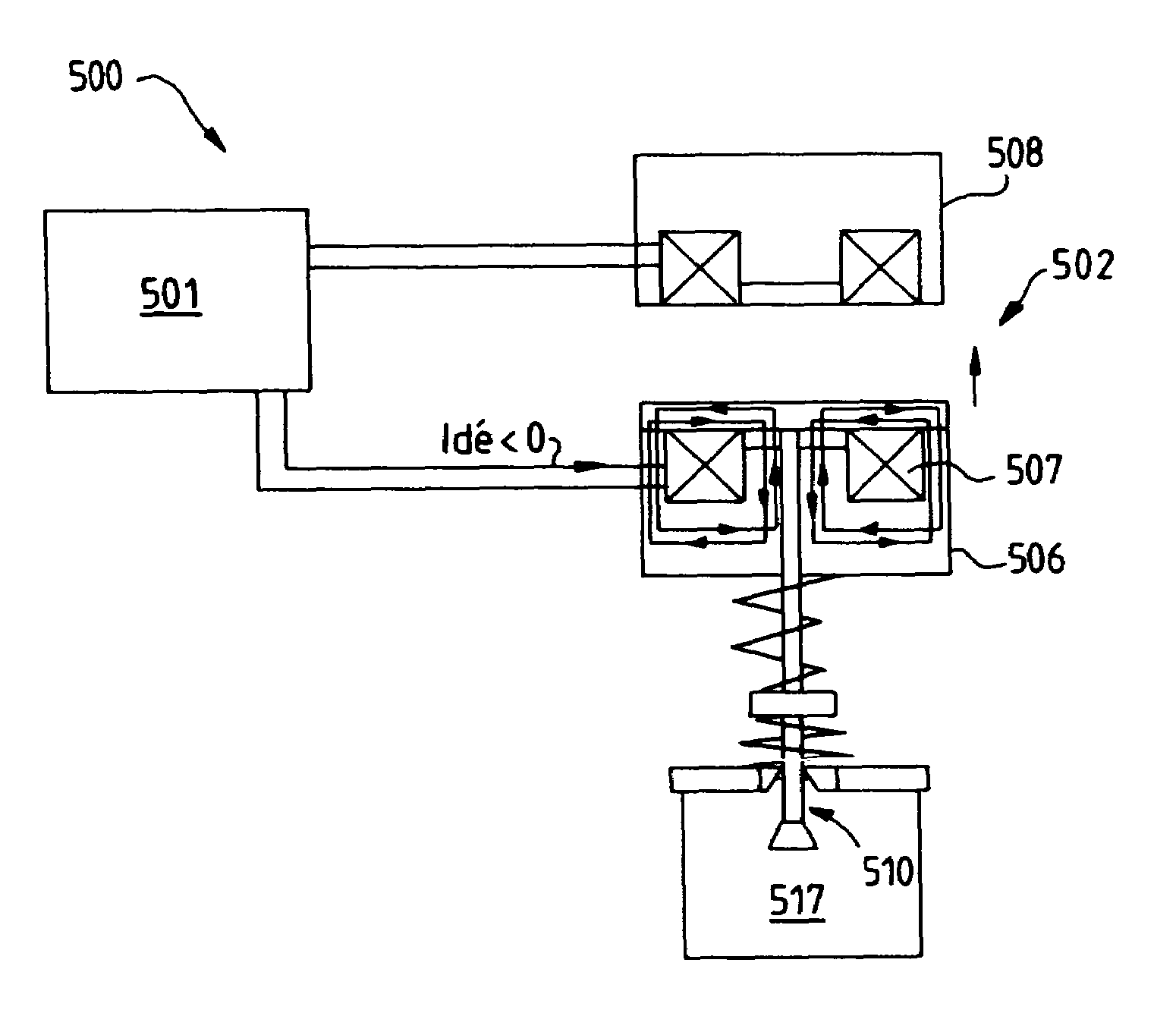
[0048]The example of the device 500 (FIG. 5) according to the present invention, which will be described below, uses a processor 501 controlling the defluxing current flowing in the coil 507 of the electromagnet 506 of an actuator 502 of a valve 510.

[0049]From another processor (not shown) or internally, i.e., from the same processor 501, this processor 501 receives a command for opening the valve 510, which determines the moment and the duration of the opening.

[0050]Based on this open time, the processor 501 determines the rapidity with which the opening and / or closing of a valve must take place taking into account that, as will be described in detail below on the basis of FIGS. 6a and 6b, the rapidity required for opening a valve depends on the duration dt of opening of that valve.

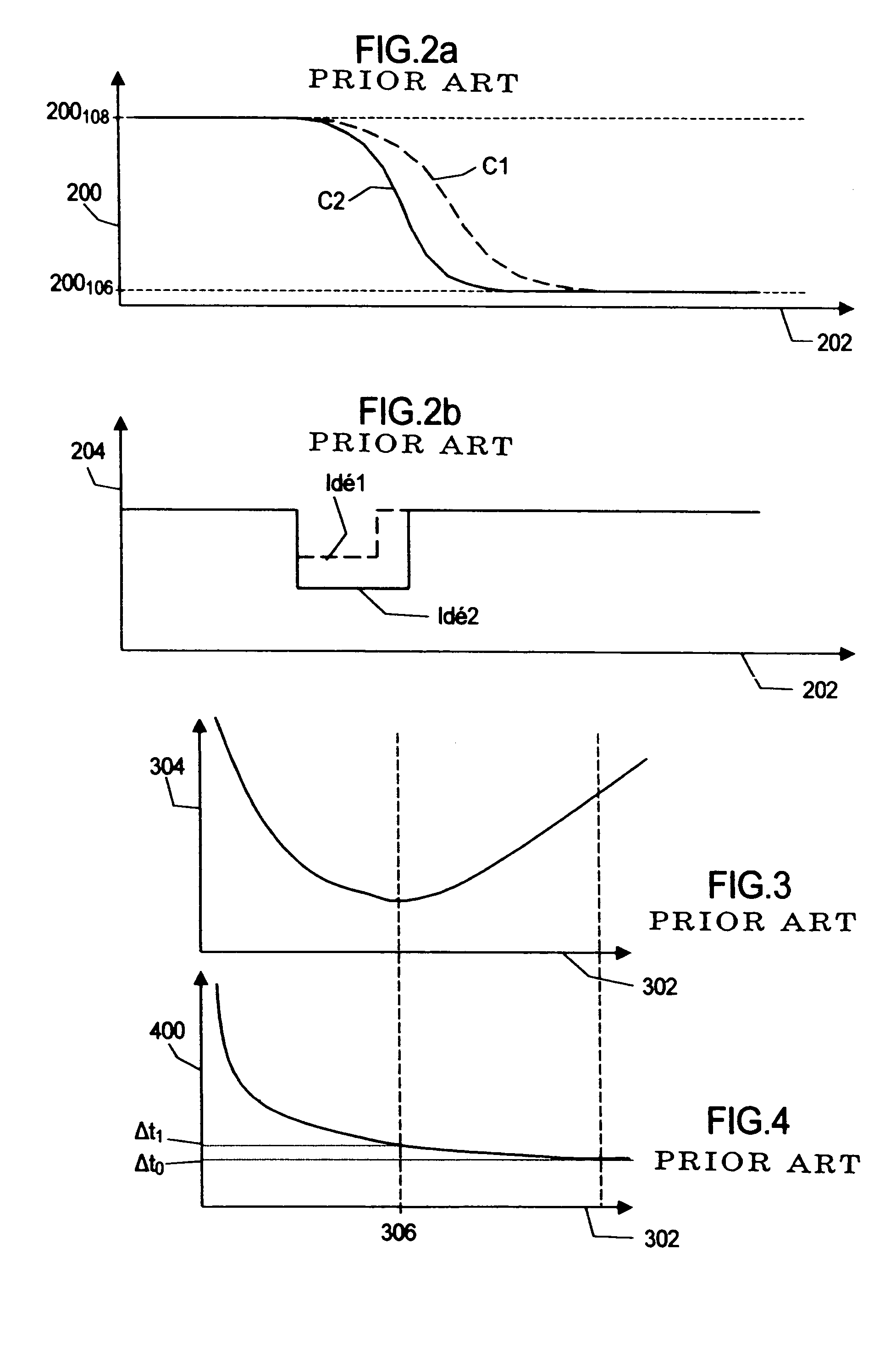
[0051]The durations dt are shown considering a first defluxing current Idé1 (curve drawn in dotted line) and a second defluxing current Idé2 (curve drawn in solid line) of an intensity and duration that ...


PUM


Abstract

The present invention pertains to a device for controlling a valve of an internal combustion engine, the device comprising an electromechanical actuator equipped with a magnet, and a processor controlling a defluxing current generating a magnetic field opposed to the magnetic field of the magnet, characterized in that it comprises means for controlling this defluxing current as a function of the open time of the valve and means for determining the rapidity of opening and / or closing of the valve from this open time, the controlled defluxing current ensuring the determined rapidity of opening and / or closing.

Description

FIELD OF THE INVENTION[0001]The present invention pertains to a valve control device for an internal combustion engine and to an internal combustion engine comprising such a device, especially for controlling a valve by means of an electromechanical actuator equipped with a magnet.BACKGROUND[0002]A device 100 (FIG. 1a) equipped with an electromechanical actuator 102 for a valve 110 comprises, in general, springs 102 and 103 and electromagnets 106 and 108 for controlling the position of the valve 110 by means of electric signals controlled by a processor 101.[0003]More specifically, these electric signals comprise currents intended to generate magnetic fields that permit the valve 110 to be displaced or maintained in a given position.[0004]The rod of the valve 110 is pressed for this purpose against the rod 112 of a magnetic plate 114 that is movable between the two electromagnets 106 and 108 in order for the plate to be displaced or maintained in such a position that the valve 110 i...

Claims


Application Information

Patent Timeline
IPC IPC(8): F01L9/04F01L9/20
CPCF01L9/04F01L9/20
Inventor MORIN, CEDRIC
Owner PEZHO SITROEN AUTOMOBILS SA
Why Eureka
Try Eureka