
Respiratory humidification system

a humidifier and respiratory system technology, applied in the direction of instruments, heating types, specific gravity measurement, etc., can solve the problems of insufficient use, inability to meet the needs of patients, and inability to achieve accurate flow readings

Active Publication Date: 2006-05-16
FISHER & PAYKEL HEALTHCARE LTD
View PDF4 Cites 101 Cited by
  • Summary
  • Abstract
  • Description
  • Claims
  • Application Information

AI Technical Summary

Benefits of technology

[0006]It is, therefore, an object of the present invention to provide a housing for a sensor which will go at least some way towards overcoming the above disadvantages or which at least provide the industry with a useful choice.
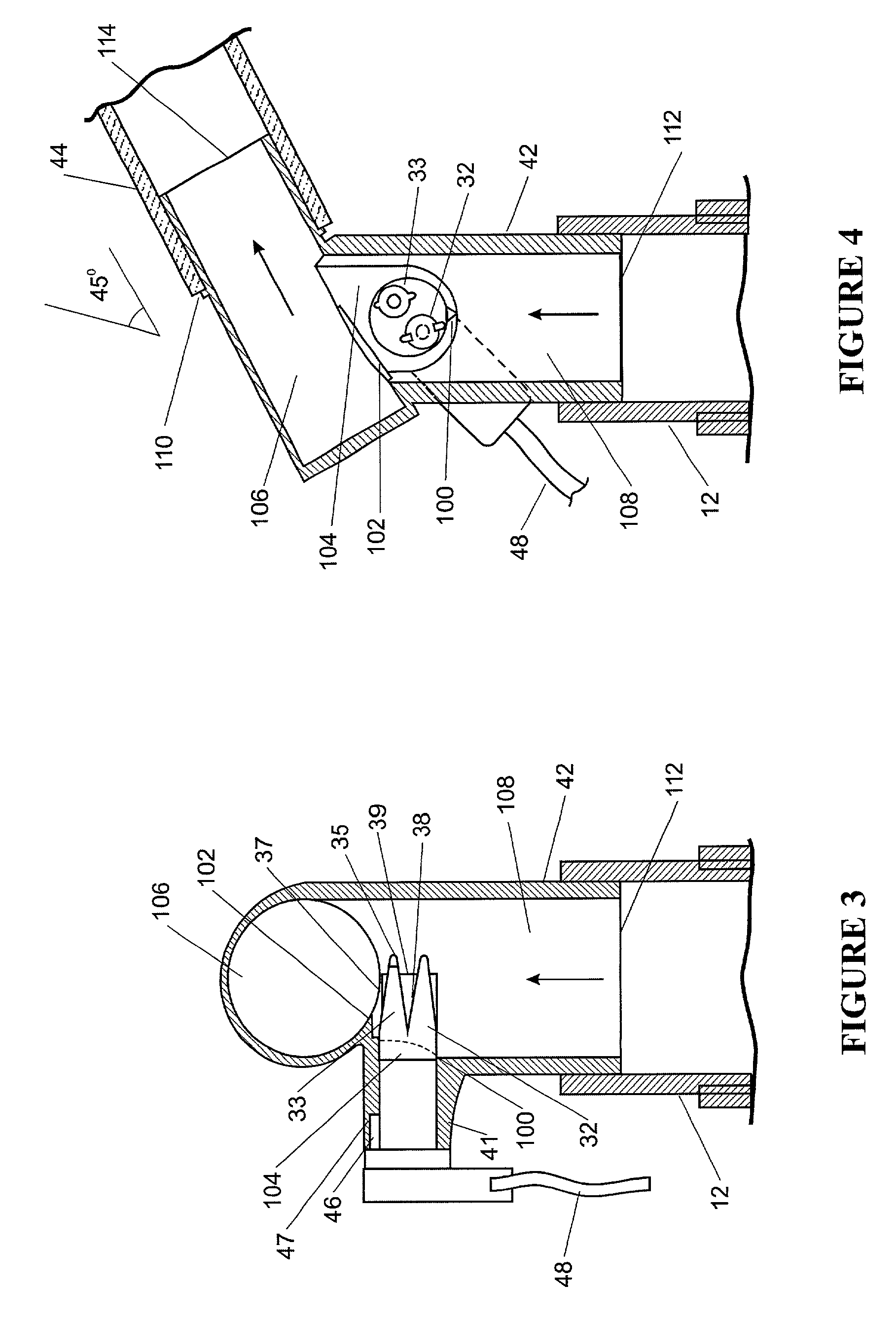
[0024]Preferably at least a portion of said second passageway including a roughened surface adapted to prevent the beading and allow continuous run-off of any condensation forming within said second passageway.
[0025]Preferably said second passageway also including an anti-fogging agent to further prevent the beading and allow continuous run-off of any condensation forming within said second passageway.
[0026]Preferably at least a portion of said first passageway including a roughened surface adapted to prevent the beading and allow continuous run-off of any condensation forming within said first passageway.
[0027]Preferably said first passageway also including an anti-fogging agent to further prevent the beading and allow continuous run-off of any condensation forming within said first passageway.

Problems solved by technology

The dependency on temperature sensors in this control method means that incorrect placement or connection of the temperature sensors can lead to impaired performance of the entire humidification and breathing system.
Lack of flow sensors which, if provided, would enable certain breathing circuit conditions to be easily recognised and appropriate action to be taken by the humidification device (and / or the gases supply).
Flow sensors have previously not been utilised in humidification systems due to insufficient robustness and problems of condensation occurring on the flow sensor, leading to incorrect flow readings.
Gases being supplied to the patient at a temperature / humidity combination which is inappropriate.
Temperature sensing alone can not ensure that these required temperature / humidity values are achieved.

Method used


Image

  • Respiratory humidification system
  • Respiratory humidification system
  • Respiratory humidification system

Examples


Embodiment Construction

[0041]With reference to the accompanying drawings and in particular to FIG. 5, an example humidification apparatus or respiratory humidification system incorporating preferred embodiments of the present invention is illustrated. Included in the respiratory humidification system is a ventilator or gases supply means or blower 1 having an outlet 2 which supplies gases (for example oxygen, anaesthetic gases or air) to the inlet 3 of a humidification chamber means 4 via a conduit 6. Humidification chamber means 4 may, for example comprise a plastics formed chamber having a metal base 7 sealed thereto. Humidification chamber 4 is adapted to hold a volume of water 8 which is heated by a heater plate means 9 under the control of controller or control means 11 of a humidification device or humidifier 10.

[0042]As the water within chamber 4 is heated it will slowly evaporate, mixing water vapour with the gases flow through the humidification chamber from ventilator 1. Accordingly, humidified ...


PUM


Abstract

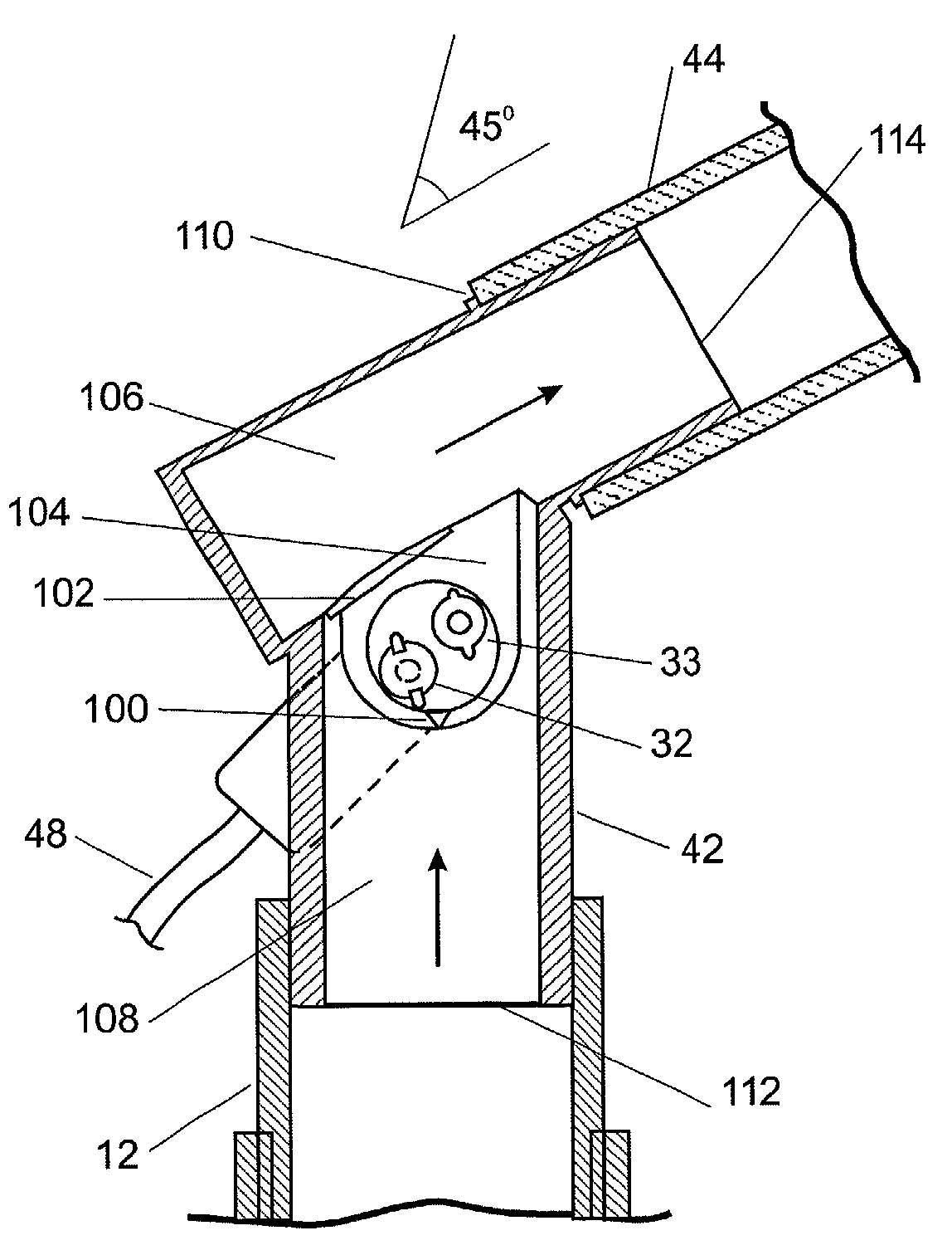
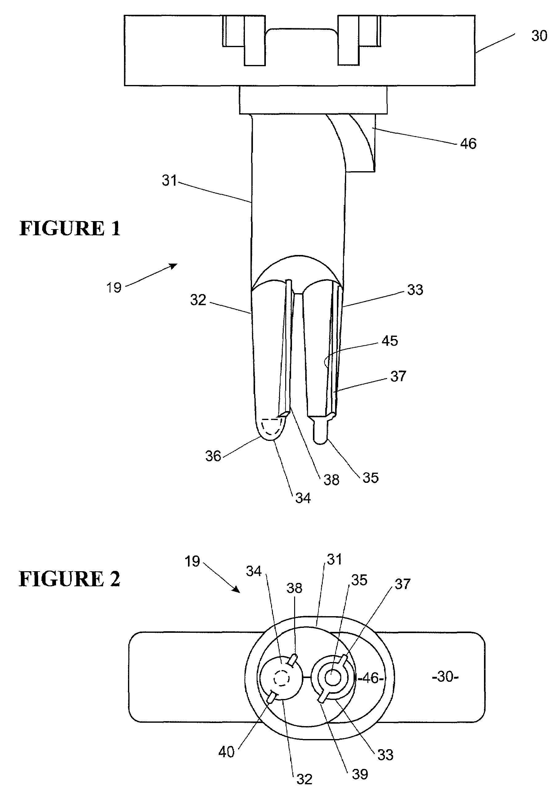
A housing for a sensor to prevent condensate from collecting in the sensor. The housing includes a deflector to channel condensate forming in the housing away from the sensor. A notch is provided at the base of the sensor to ensure any condensate forming on the sensor itself does not collect at the sensor base. Further the interior of the housing is roughened and treated with an antifogging agent to ensure any condensate falls continuously so droplets do not form.

Description

FIELD OF THE INVENTION[0001]This invention relates to gases distribution systems and in particular, though not solely, to respiratory humidifier systems which humidify gases for a patient, or other person in need of such gases, to breathe.BACKGROUND ART[0002]Many, if not all, existing active respiratory humidification systems which deliver humidified gases (such as oxygen or anaesthetic gases) to a patient, or other person in need of such gases, operate as temperature controllers. That is, the temperature of the gases leaving the humidification device is monitored and the heat source controlled in response to changes in that temperature to achieve a desired outgoing humidified gases temperature. An example of this type of humidifier control system is disclosed in our prior U.S. Pat. No. 5,558,084. This method of control has a number of disadvantages.[0003]The dependency on temperature sensors in this control method means that incorrect placement or connection of the temperature sens...

Claims


Application Information

Patent Timeline
Patent Type & Authority Patents(United States)
IPC IPC(8): G01F1/68A61M15/00F24F6/00A61M16/00A61M16/10A61M16/16G01F1/684
CPCA61M16/1075A61M16/16A61M16/1095G01F1/6842A61M16/109A61M16/0066A61M2205/3368A61M2016/0039A61M16/0841A61M16/161
Inventor SMITH, MALCOLM DAVIDLEONARD, PETER JOHN
Owner FISHER & PAYKEL HEALTHCARE LTD
Learn More