Shock-proof electric marine engine, e.g. engine or generator

a technology of electric marine engines and generators, applied in the direction of magnetic circuit rotating parts, vessel construction, magnetic circuit shape/form/construction, etc., can solve the problems of particularly severe shock acceleration of electric marine machines in electrical steering propellers, and achieve the effect of avoiding dockyard time, robust, and shock-resistant configuration

Inactive Publication Date: 2006-04-18
SIEMENS AG
View PDF14 Cites 15 Cited by
  • Summary
  • Abstract
  • Description
  • Claims
  • Application Information

AI Technical Summary

Benefits of technology

[0009]In another refinement, an embodiment of the invention provides for the housing to be arranged on an elastically mounted base frame inside the vessel, with the propulsion shaft having an elastic coupling to a propeller shaft or a water jet impeller shaft. This results in an embodiment of a marine machine which, even when mounted in the interior of the vessel, can withstand, for example, a mine explosion or the impact of a missile, which causes severe vibration in the vessel. This therefore avoids generator failure when the shock-resistant electrical marine machine is in the form of a generator. This therefore results in twice as much elasticity with respect to the hull of the vessel both for the electrical marine machine in the interior of the vessel and for the marine machine which is arranged in an electrical steering propeller.
[0019]For electric motors of this type, which are installed in the vessel, an embodiment of the invention advantageously provides for the stator to be designed such that it can rotate in the housing via slide rings, for example by way of a stator yoke which can rotate. It is thus possible to carry out any necessary repairs that may be required, for example on the cooling system, without having to completely disassemble the machine, and without the machine having to be removed as an assembly and disassembled. This is particularly advantageous for a shock-resistant electrical marine machine for a navy vessel, since this makes it possible to avoid dockyard time. There is no need to remove the machine in order to work on the stator.

Problems solved by technology

An electrical marine machine in an electrical steering propeller is subject to particularly severe shock accelerations since, in some circumstances, a mine or a torpedo may explode directly underneath the electrical steering propeller.

Method used


Image

  • Shock-proof electric marine engine, e.g. engine or generator
  • Shock-proof electric marine engine, e.g. engine or generator
  • Shock-proof electric marine engine, e.g. engine or generator

Examples


Embodiment Construction

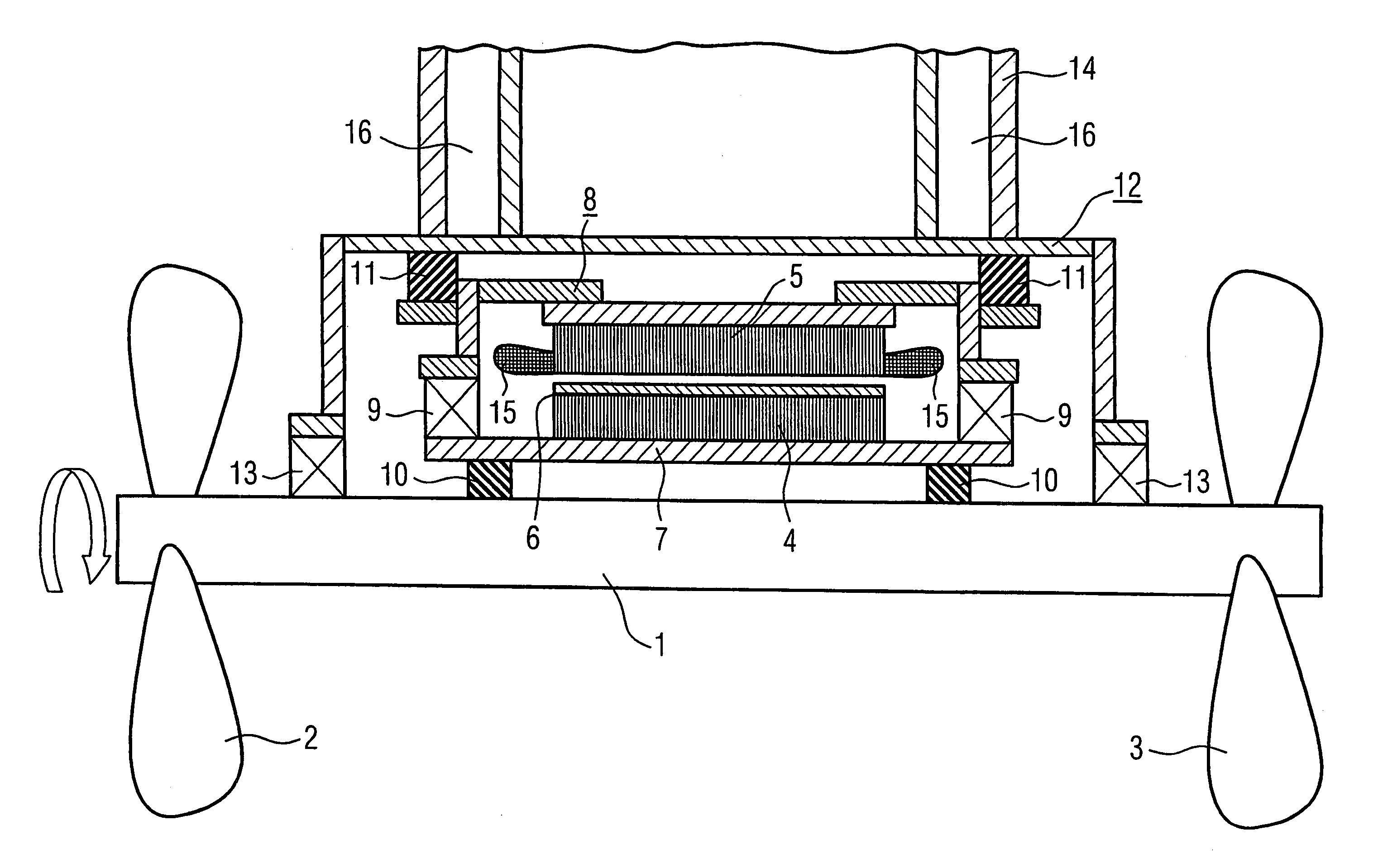
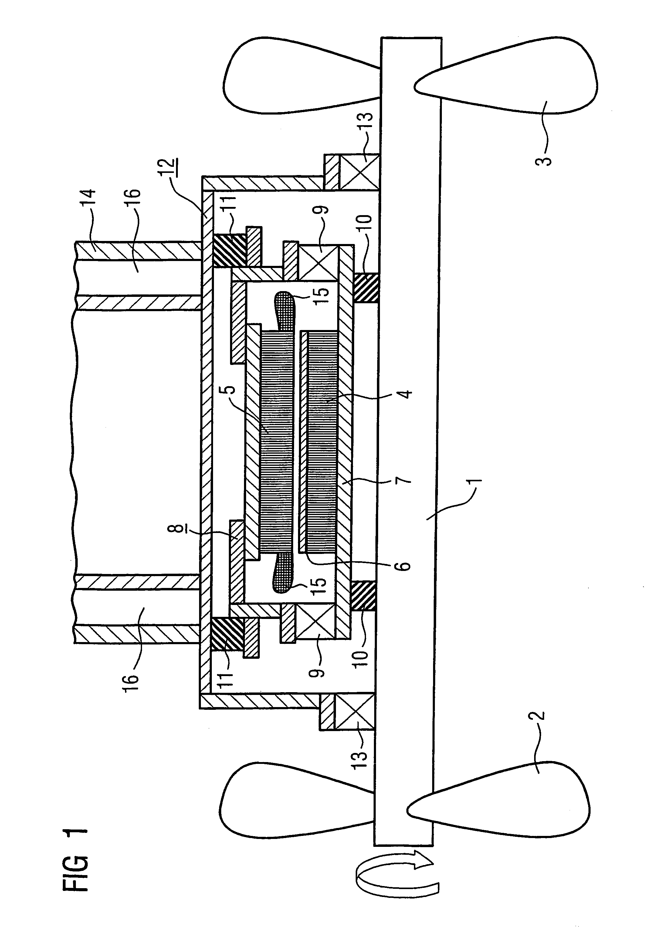
[0027]FIG. 1 shows the propulsion shaft 1 of a motor or tubular generator for a navy marine machine, with the propulsion shaft 1 having one propeller 2 or 3 at each end. Only the upper half of the electric motor which drives the propulsion shaft 1 is shown, in the form of a section. This electric motor includes a rotor 4 and a stator 5, with the rotor having an electromagnetically active layer 6 in the form of permanent magnets, and being arranged on a tube-like mounting body 7. The stator 5 has a mounting housing 8 which is in two or more parts and is fixed via rotating bearings 9 on the mounting body 7 for the rotor.

[0028]The unit including the rotor 5 and the stator 6 is supported by way of elastic damping elements 10, 11 firstly on the propulsion shaft 1 and secondly on a housing 12 which holds the electric motor and the propulsion shaft. The propulsion shaft 1 is in this case mounted via rotating bearings 13 in the housing 12.

[0029]The housing 12 has a mounting casing (casing) ...


PUM


Abstract

A shock-proof electric marine engine, e.g. an engine or generator, is for a marine (Navy) ship, and includes a stator and a rotor in a housing. The stator and the rotor are connected in such a way that they are rotatably displaceable in a counter direction and in a radial / axial manner with limited slack. The rotor and stator form a displaceable unit in relation to the housing, which can be displaced away from the housing with a higher vibration overshoot range. The housing is elastically connected to the marine (navy) ship.

Description

[0001]This application is the national phase under 35 U.S.C. § 371 of PCT International Application No. PCT / DE02 / 03242 which has an International filing date of Aug. 30, 2002, which designated the United States of America and which claims priority on German Patent Application numbers DE 101 43 713.7 filed Aug. 30, 2001, and DE 102 24 014.0 filed May 29, 2002, the entire contents of which are hereby incorporated herein by reference.FIELD OF THE INVENTION[0002]The invention generally relates to a shock-resistant electrical marine machine, for example a motor or generator, for a navy vessel; preferably one which has a stator and a rotor in a housing, with the rotor being connected to a propulsion shaft.BACKGROUND OF THE INVENTION[0003]Vibration-damped electrical marine machines, for example motors, are known, for example from WO 02 / 30742 A1. In order to damp vibration, the rotor and the stator in the known motors are supported on one another, and the stator is supported on the motor ho...

Claims


Application Information

Patent Timeline
Patent Type & Authority Patents(United States)
IPC IPC(8): B60L11/02B60L50/10B63G13/00B63H5/125B63H21/17B63H23/24H02K1/18H02K1/30H02K5/24H02K7/08H02K7/12H02K7/18H02K9/19H02K55/04
CPCB63H23/24H02K1/185H02K1/30H02K5/24H02K7/08H02K7/088H02K55/04B63H5/125B63G13/00Y02T70/5263B63H2005/1258B63H2021/173H02K7/083H02K7/12H02K9/19Y02T70/50Y02T10/70B63H21/38H02K5/20
Inventor BRACH, KARSTENHEIN, PETERHOFMANNKRUGER-GOTZMANN, MANFREDMEYER, CHRISTIANSCHILLER, CHRISTIANVOGELEY, PETERWILCKE, RALF
Owner SIEMENS AG
Why Eureka
Try Eureka