Customized orthopedic sole-insert and method for making

a technology of orthopaedic inserts and inserts, applied in the field of orthopaedic inserts, can solve the problems of muscle fatigue, inability to work properly, and inability to control the alignment of the lower extremities, and achieve the effect of prolonging the length of the foo

Active Publication Date: 2006-03-28
MADDUX MELVIN
View PDF11 Cites 16 Cited by
  • Summary
  • Abstract
  • Description
  • Claims
  • Application Information

AI Technical Summary

Benefits of technology

[0012]1. To provide a method for making a customized a sole-insert for a shoe quickly using a layer of formable material which can be permanently hardened once a customized shape is obtained;
[0033]In the preferred embodiment, there are several cuts about 0.5–1.0 cm into the periphery of the shell to allow for minimal flex when downward weight is applied during the fitting or molding process. These cuts serve to avoid distorting the shape of the sole insert during the fitting process.

Problems solved by technology

This mechanism will not function properly if the bones and joints of the person's foot and ankle are in abnormal alignment.
If such an abnormal alignment is present, muscles in the lower extremities will be required to work harder to control the alignment of bones and joints.
As a consequence, these muscles will fatigue quicker.
Once muscles fatigue, the person will experience pain and discomfort because the muscles can no longer compensate for the abnormal alignment of the foot and ankle.
This type of procedure is expensive, and requires a substantial amount of time between the initial plaster cast and the final product; sometimes on the order of weeks.
Also, due to the expense, a patient normally can not afford additional inserts and will typically use the same insert when wearing different shoes.
Although this method is workable, the marketplace is desirous of a more simpler design and method.

Method used


Image

  • Customized orthopedic sole-insert and method for making
  • Customized orthopedic sole-insert and method for making
  • Customized orthopedic sole-insert and method for making

Examples


embodiment

Semi-Rigid Shell Embodiment

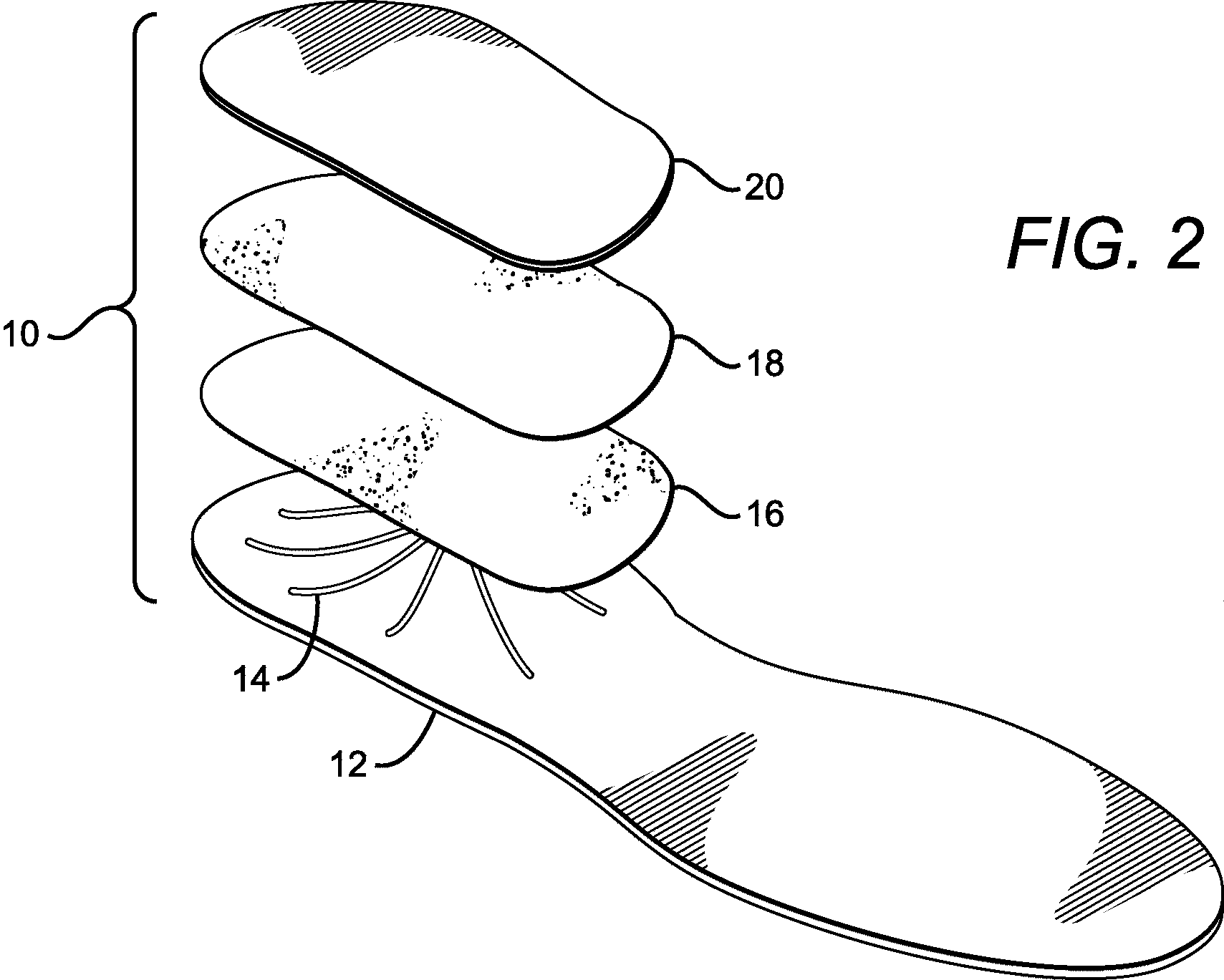
[0059]FIG. 6 illustrates an exploded view of my insert 110. A bottom shell 112 is constructed of a pre-made shell having a contoured arch. Shell 112 is formed from a thin layer of fiberglass or alternatively is injection molded with a hard plastic material such as high density polyethylene. The top surface of shell 112 has a plurality of canals 114 that extend from aperture “A” as shown in FIG. 6 and FIG. 9. Aperture “A” extends from the top surface to the bottom surface of shell 112 as illustrated in FIG. 8. Aperture “A” is positioned in the arch area of the insert as shown in FIG. 10.

[0060]FIG. 8 illustrates a cross sectional view of insert 110 taken along line 8—8 of FIG. 7. Positioned upon the top surface of shell 112 is a sponge layer 116 for temporarily absorbing the hardening agent and for subsequent distribution in the manner described earlier for the soft-shell embodiment. Positioned upon sponge layer 116 is a formable layer 118 comprising a suffi...


PUM

PropertyMeasurementUnit
thicknessaaaaaaaaaa
thicknessaaaaaaaaaa
sizesaaaaaaaaaa

Abstract

A method for making a customized sole insert for a user is disclosed. The insert is first manufactured in various sizes, widths and arch heights so that a user may select the insert best configured for his foot. The insert is initially comprised of a bottom layer or shell; a formable layer which can be hardened into a particular shape; and a top cushion layer for contact with a wearer's foot or sock. The shell has an aperture for injecting a hardening agent to accelerate the hardening of the formable layer. After the insert is selected, the hardening agent is injected through the aperture and the wearer stands upon the top cushion layer until the formable layer has hardened. The result is a formable layer which is substantially conformed to the plantar aspect of the wearer's foot.

Description

BACKGROUND OF INVENTION[0001]This invention relates to orthopedic inserts for a shoe and a method to customize the insert for a particular user quickly and efficiently.[0002]The human foot is a unique structure that can be very flexible or very rigid when a person walks depending upon the internal locking and unlocking mechanism of the bones and joints in the person's foot.[0003]This mechanism will not function properly if the bones and joints of the person's foot and ankle are in abnormal alignment. If such an abnormal alignment is present, muscles in the lower extremities will be required to work harder to control the alignment of bones and joints. As a consequence, these muscles will fatigue quicker. Once muscles fatigue, the person will experience pain and discomfort because the muscles can no longer compensate for the abnormal alignment of the foot and ankle.[0004]There have been many developments in the prior art addressing abnormal alignment of the foot and ankle. Besides inv...

Claims


Application Information

Patent Timeline
Patent Type & Authority Patents(United States)
IPC IPC(8): A43B13/38B29B15/10A43B7/28
CPCA43B17/107A43B7/28A41B11/12
Inventor NGUYEN, TIM THE
Owner MADDUX MELVIN
Why Eureka
Try Eureka